No - the hum has nothing to do with adjustment. The 50-60 Hz hum is connected to the way of groundwiring. The generated hum is very difficult to find without oscilloscope...therefore asking for schematic of the original TVA-1 groundplan. Where did M&A place central gnd. and why is the RCA input connectors not isolated from chassis? odd.
I really do not know how to help you as I do not have the original TVA-1 schematic. You can have it from the net where you can search.
I do hear from this forum that someone has the hum one one channel and when swapping the KT88 from the right to the left, the hum moves to the left. This incident proves that the hum comes from the KT88 tube.
May be your cause of hum could be the cause of the tubes. Just my opinion.
I do hear from this forum that someone has the hum one one channel and when swapping the KT88 from the right to the left, the hum moves to the left. This incident proves that the hum comes from the KT88 tube.
May be your cause of hum could be the cause of the tubes. Just my opinion.
Thank you very much. Your information definately very very useful for me as I try to build it TVA-1 crone from scratch. I try to secure the custom power supply transformer as well as the output transformer from manufacturer in China.
The output transformer with the secondary winding as 0-4-8ohms and 0-16 ohms. It has 2 sets of windings. I wonder whether each set should work out with 70 w output, if so means 0-4-8ohms output 70w and 0-16ohms output 70w. this case, it may turn out to be 140w? Does it calculate this way?
I understand, in order to have good sound, one should work out more power on the output transformer and so I asked for 80w output instead.
Any advise, please. Thanks.
No- the two KT88's "sees" into Raa on the primary of the OP's. The load on the secondary could be 4 Ohm , 8 Ohm or 16 Ohm..... . The load will affect the wattage output , but you can't add 70watt for 8 Ohm with 70 watt for 16 Ohm. One load only...normally the 16 Ohm's winding used for FB.
According to schematic drawing, the o/p trans on secondary is 0 - 4 - 8ohms and 0 - 16 ohms. I told the manufacturer that two sets (0 - 4 - 8ohms and 0 - 16 ohms) should be same size of windings. I hope I got it right.
No, they're not, the 0 - 4 - 8 will have a total number of windings that is 0.707 the number of windings present on the 0 - 16 ohm winding. Another way to look at it is that the 8 ohm winding has about 71% the number of turns that should be found on the 16 ohm winding. The wire gauges should be sized for the higher currents found in the lower impedance outputs. (4 ohm tap delivers twice the current/half the voltage for a given output power as does the 16 ohm tap)
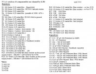
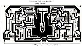
TVA-1 componentlist, wiring, driver PCB etc.
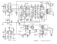
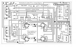
For repair and troubleshooting of the famous TVA-1 valve Amplifier from Michaelson & Austin , KJ2005 has drawn a diagram of the wiring seen from the bottom of the amplifier.
KJ2005 has been excluded from diyaudio.com by the moderator and owner, for no reason at all.
In order to help all TVA-1 owners this should be the first time that both the driver PCB, bias PCB, component list and hardwiring diagram is available for TVA-1.
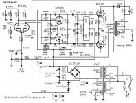
Schematic taken from TVA-1 serial no. 553
Notes:
The 2016 wiring drawing is taken from Michaelson & Austin TVA-1 serial no.16 and there may be changes in component values at later amplifier versions.
Secondly : The owner of TVA-1 serial no.16 has changed the connections on the outputtransformers from 8 Ohm to 4 Ohm.
When available the original 8 Ohm wiring on the Partridge OP-transformers shall be shown in this thread.
For repair and troubleshooting of the famous TVA-1 valve Amplifier from Michaelson & Austin , KJ2005 has drawn a diagram of the wiring seen from the bottom of the amplifier.
KJ2005 has been excluded from diyaudio.com by the moderator and owner, for no reason at all.
In order to help all TVA-1 owners this should be the first time that both the driver PCB, bias PCB, component list and hardwiring diagram is available for TVA-1.
Schematic taken from TVA-1 serial no. 553
Notes:
The 2016 wiring drawing is taken from Michaelson & Austin TVA-1 serial no.16 and there may be changes in component values at later amplifier versions.
Secondly : The owner of TVA-1 serial no.16 has changed the connections on the outputtransformers from 8 Ohm to 4 Ohm.
When available the original 8 Ohm wiring on the Partridge OP-transformers shall be shown in this thread.
Attachments
-
 Michaelson and austin rev. drawing 2016 incl componentlist.JPG131 KB · Views: 567
 -
 Componentlist TVA 1 2016.JPG232.5 KB · Views: 538
 -
 Driver board TVA 1 2016.JPG225.2 KB · Views: 491
 -
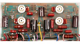 tva1 photo driver PCB componentlist 2016.JPG324.2 KB · Views: 443
 -
 TVA- driver PCB fra loddesiden 2016.GIF87.4 KB · Views: 450
 -
 TVA1 biasprint 2016.GIF54.3 KB · Views: 307
 -
 TVA-1 wiring 2016 by KJH.JPG186.5 KB · Views: 400
......you're welcome
For my friend.........
If anyone read this, I would like to know approximately how many copies Michaelson & Austin made of the well known TVA-1 poweramplifier?
From some japanese sites I found serial numbers above 2100 pcs.
Another question is the size of the main transformer (AC). On the erly TVA-1 versions the main transformer is smaller (lower) than the outputtransformer. Up to serial no. 553 the main AC transformer is still the smaller type. At which serial number changes the size of the main transformer on TVA-1?
At the point of ( larger main transformer) the TVA-1 serial number where the heater current was increased, the secondary tapping points on the main transformer also changed.
The smaller main transformer had 0 - 400 - 440Vac on the secondary and 0V - CT - 6,3Vac for all heaters (thats it). ......minor change on serial no. 553 where 0 - 370Vac was added....
The later versions (larger size) of main transformers had 190 - 0 - 190Vac , 0 - 12 (KT88)- 100Vac(bias) and 6,3Vac for ECC81,83
Any information would be highly appreciated.
.....Gudmund , thanks for asking these questions for me, and letting me borrow your account. Regards Kim
I compared Torben's schematic of the power supply to mine this weekend and it is in fact exactly that. Would anyone be able to assist me in getting the appropriate specs for the NTC (thermistor) to replace the one in my amp? The body of mine was cracked and I took it out some time ago and subsequently misplaced (lost) it. Sadly I lack the knowledge to come up with the appropriate specs myself. I appreciate any help.
TIA
Paul
Hi Paul,
If you are still working with your TVA-1 amplifier, I should inform you from Kim, that all details concerning the circuit is now available. The special inrush 416 R ntc resistor will be hard to find these days.
The central ground on your TVA-1 was located exactly the same place on the serial no. 16.
You have been most kind...thanks for sharing your pictures from the bottom of your TVA-1.
")
Best regards Gudmund
TVA-1 serial no.16
recieved from KJ2005 .......
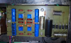
An early TVA-1 serial no.16 from Michaelson & Austin renovated and the actual amplifier schematic circuit written down including measured voltages...
Note changes of resistor values in the bias circuit.......
Gold Lion KT88's running smoothly at 36mA by 525V........
recieved from KJ2005 .......
An early TVA-1 serial no.16 from Michaelson & Austin renovated and the actual amplifier schematic circuit written down including measured voltages...
Note changes of resistor values in the bias circuit.......
Gold Lion KT88's running smoothly at 36mA by 525V........
Attachments
Does somebody know how the delay relay is supposed to work? I mean I can see that it counts up to 40.96 seconds in the 4020 and then grounds the PSU earth, but in the meantime the HT has been about +100V and the negative bias about -750V, which isn't good for anything; then when the relay kicks in the HT correctly goes to +560V, but the negative bias goes to ZERO, which causes massive plate current to flow, then sinks down to the correct level (-75V in my case) over 10-15 seconds. Which blows the T0.5A HT fuse sometimes. This cannot be right. Any clues? I've changed the bias pots and resistors around them to something like VR=22K and 39K to ground, so as to get a bias adjustment range of -75 to -48V for various valves the owner is planning on, and I put in the above-mentioned 16R NTC resistor, but no other changes.
Well I never did fgure that out, but I changed the cathode resistors to 100R, which controls the inrush to something 200mA for only a few seconds, then it sinks down to 36mA as the negative bias comes on. It results in 3.6V on the cathode when correctly biased for 36mA, so it doesn't have too much effect on the bias chain values. If I was doing it over again, which I won't, I would use 150R or even 220R, and if I was really doing it all over again I would use 1K2 and get rid of the negative fixed bias chain altogether.
Hi Folks,
Sorry to rattle an old cage, but does anybody know what the Ra-a input impedance of the TVA-1 amplifier's output transformers was ?
i know it had two separate seconday windings: 0-4-8 ohms for speaker output and 0-16 ohms used for feedback to the input/phase splitter stage.
The thing is, was the Ra-a the standard datasheet 4kΩ, 5kΩ, 6kΩ, 4.5kΩ or what ?
i personally suspect it was 4.6kΩ, having had a pair wound many years ago.
Neil xx.
Thanks to the mods for re-opening this thread.
It seems to be the most complete for Michaelson & Austin TVA-1 issues.
For repair consider the schematic that A. K made, first attachment :
https://www.diyaudio.com/community/threads/tva-1-export-circuit-schematic.131000/#post-2324542
A factory schematic is in post 24 here :
https://www.diyaudio.com/community/threads/michaelson-austin-tva-1-info.123806/page-2#post-2016244
I had a look at my personal service notes today :
In early schematics like that in post 1 you see the voltage for output tubes heater
is described as 12 V and in fact each channel tube filaments are wired in series. I
found this was a bad idea and added a centre string between channels at the points
where two tube filaments are connected.
I seem to remember I grounded this new centre instead of one of the transformer
wire ends. The added wire also helps to balance the filament voltage distribution.
Since in the diagram of post 1 the negative bias voltage is derived here you would
want to check any change in this respect also.
This model has useless fuses in the speaker outputs. The fuse holders are of bad quality.
I replaced them and rewired as plate fuses.
A connection of pin 8 with pin 1 (suppressor grid) on all output tube sockets is useful,
because many people use this amp with EL34 tubes.
I disconnected the ground wire of the small signal tubes heaters and made a "balanced"
wiring using the standard 100 ohms pot with wiper to ground - you have to find a suitable
place for it.
All in all these changes made the operation of model TVA-1 more reliable.
- Home
- Amplifiers
- Tubes / Valves
- Michaelson & Austin TVA-1 info