Thanks for the feedback. Comforting to know.
I didn't see any problems with the offset on the output, so I was pretty sure it was OK.
The shunt regulator is dead silent I had problems finding any noise on the scope (highest resolution is 2 mV/div and at this setting I could barely make out some fuzz on plot, certainly less than 0.5mV). Thanks for the brilliant design. I'm thinking this would be great in a DAC.
the Mez is sitting on my desk right now. Without any load, the fins on the IRFs are not even warm.. Makes me want to try a 9R hotrod (200 mA = ca 4 x current) with some more sinking.
I'm thinking of putting it into a case together with an ODAC (USB) and an optical/Coax DAC (not yet decided, recommendations are welcome) to give me 4 analog + 2 digital inputs making it an All-in-one stereo Preamp..
I guess I could run the DAC off a second shunt reg powered by the same transformer, no?
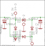
If you will go directly to the filter caps positions you can feed DC there. Use some cap there at least 100uF to decouple the incoming DC wiring. Watch the polarities. You don't need to populate the diode positions or the Tx connector anymore of course.
Thanks Salas,
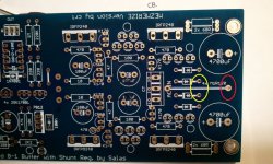
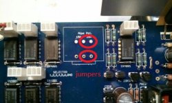
Just to make it perfectly clear to me, 'cause I don't want to screw this up and I'm unsure of what I'm doing, please confirm this for me. Photo below.
1) The capacitors SHOULD be installed + / - as labeled on the board. (Caps are 4,700 uF 35V Nichicon Gold Tone)
2) The Red circle should be connected to the - negative DC input
3) A jumper installed across the Green oval , and the + Positive DC input should be connected here.
4) All jumpers on board (to connect -) should be installed.
Don't short AC-in jumper with + jumper at Green oval ( 8-0 )
Do I have this correct?
Thank you VERY much for your help.
Ron
Attachments
Last edited:
1. Install 100uF 35V wiring decouple capacitors where the 4700uF are designated. If you want heavier local caps, your choice. White stripes are (-). Used to be a rock band duo also but that's OT.
2. You connect incoming GND wire from your other board raw supply there, see pics.
3. No new jumper in the specific area than the long white one. In double sided boards should be a via under the white ink also if you will do a continuity check with your DMM, but do reinforce it. All other printed jumpers ditto.
Attachments
Salas,
Thank you for your help, I understand now.
White Stripes?
Red Stripe.........Yeah BEER!
I'm sure I'll have more questions as I progress, as it turns out my Primary PS doesn't output enough mA for a HOT ROD build. I was hoping not to run the A/C wires from the TX to the board. Careful detail to routing the wiring should work.
Thank you for your continued help with this thread.
Ron
Thank you for your help, I understand now.
White Stripes?
Red Stripe.........Yeah BEER!
I'm sure I'll have more questions as I progress, as it turns out my Primary PS doesn't output enough mA for a HOT ROD build.
I was hoping not to run the A/C wires from the TX to the board. Careful detail to routing the wiring should work.Thank you for your continued help with this thread.
Ron
Back with more questions again.
What is the maximum recommended input voltage for the Mez?
I have an R-Core with (2) 15V secondaries, when I tie the outputs to make a CT, I have 37 Volts from rail to rail. This is unloaded Voltage. The power Company pushes the voltage higher than 110-115V in my area, ~123V normally, hence the 37V unloaded.
Ron
Onto the next question.
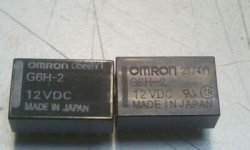
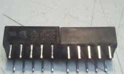
I've scrounged some Omron G6H2 relays from various sellers, Is there a way to tell if they are counterfeit?
Some have printing on the side others don't.
Got a guess?
Thank you,
Ron
I've scrounged some Omron G6H2 relays from various sellers, Is there a way to tell if they are counterfeit?
Some have printing on the side others don't.
Got a guess?
Thank you,
Ron
Attachments
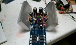
Another Hot Rod is Born.
I've measured across the 10 Ohm resistors and I get....1.406+ and 1.436- .
I'm sure it's been asked 100 times before but it's a HUGE thread. So I'll make it 101 times, where else do I measure for proper voltages? I've measured the offset (difference from neutral to L&R) on the signal pins and I get .001 and .003.
Board Voltage is 9.58 and -9.42
Thanks for a very cool LED project.
Ron
Attachments
Last edited:
Salas,Thank you again for your help and sharing your time.
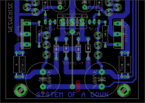
If I want to use a separate volume controller on a different board, can I jumper these two pair of outputs? I want to run the audio to a different board that has it's own attenuation.
Thank you for answering my strange questions.
Ron
If I want to use a separate volume controller on a different board, can I jumper these two pair of outputs? I want to run the audio to a different board that has it's own attenuation.
Thank you for answering my strange questions.
Ron
Attachments
- Home
- Amplifiers
- Pass Labs
- Mezmerize DCB1 Building Thread