For the antek
<snip>
Also - tie both greens together and put on 0 middle tap on board.
One blue each left and right.
It looks nice")
Not quite right, connect one blue and one green together and connect to center tap, then one blue to either left or right and the green to the remaining terminal. Connecting the two greens together results in the two windings being in phase and you end up with half wave rectification instead of full wave rectification. (I've used a lot of these transformers, and often parallel the windings in higher current applications.)
Looking at building the Mezmerize DCB1 to use as a pre-amp for an integrated amp with the classdaudio CDA-254L amp kit. Have a few questions:
- The CDA-254 amp has an input impedance of 7K. Is this a suitable match for the Mezmerize?
- To use for my headphone amp I'd very much like a "tape out". I'd like a solution that optionally mutes the speaker outputs. Can this be made?
- I would prefer to build both the Mezmerize (with toroid) and the full CDA-254L kit (amp, power supply and toroid) into the same case but am afraid of getting hum and EMI noise. Do you think it would be a better solution to place the CDA-254 amp board and the Mezmerize board in one case, and then place the toroids and the power supply board in another case? I could then just stack the two cases with the power supply in the bottom and the amp case on top.
Cheers,
Gregers
- Yes, it can drive the amp.
- You can just Y the output to a headphones amp, and there is no provision for a secondary switch controllable output relay on board. You may devise something additional if you can design and make.
-That is something depending on EMI levels of that amp. Its safer to use two cases with each circuit and its toroid in each or be willing to find out in practice.
One last question, as I am just about to power up my DCB1 for this first time, and I don't want to smoke something.
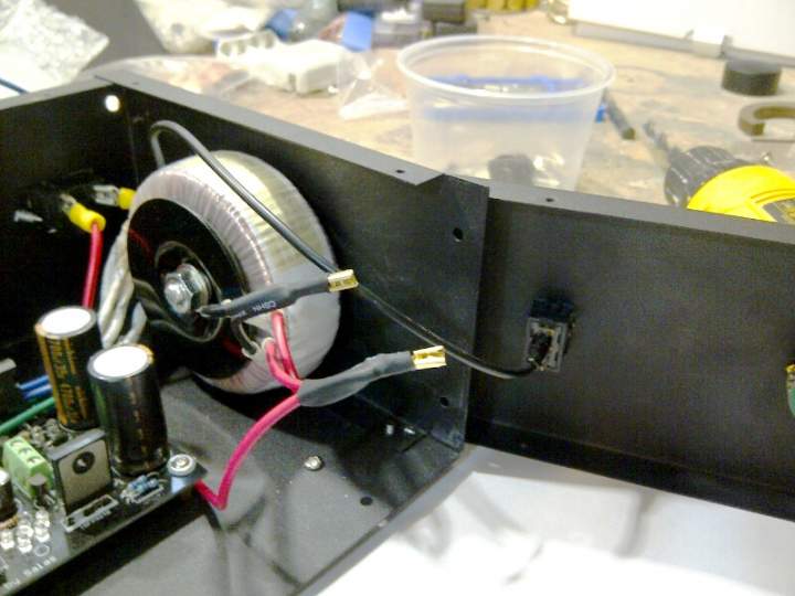
Have I hooked up the transformer correctly to the 3 prong power switch?
(Not sure if you can see the picture clearly but...)
Black wire straight from the IEC to the top of the switch.
Blacks from the transformer joined, then plugged in to the second prong of the power switch.
...and finally Red wires, as well as a live from the IEC, joined together and plug in to the bottom/last prong.
Again, its a simply thing, but man is it every confusing for someone like me who doesn’t do this often.
Again, just looking for confirmation and also be told that I won’t screw anything up if its hooked up wrong.
Before, plugging to the DCB1 board itself, I guess I should verify I get 15 V on the output first. Correct?
...and what’s the worst that can happen?
Again, thanx all for your input and hope to hear this preamp finally singing after all these weeks!
Oh, and one comment, for my 50 yr old eyes, soldering the pin connectors was a very difficult job, as thing are VERY small.
Cheers, Fred in Canada
Is it that model? http://www.antekinc.com/pdf/AN-0515.pdf
If yes, then you go red/red, black/black to live/neutral, inner blue/green to dcb1 connector's center, outer green to one outer connector's point, outer blue to the other outer connector's point. 3rd centre IEC prong you drive it to chassis. You switch black/black or red/red if with a single pole mains switch.
If yes, then you go red/red, black/black to live/neutral, inner blue/green to dcb1 connector's center, outer green to one outer connector's point, outer blue to the other outer connector's point. 3rd centre IEC prong you drive it to chassis. You switch black/black or red/red if with a single pole mains switch.
Use the bulb tester as already advised.
Power up the transformer alone through the bulb tester.
If OK add the DCB1 to the transformer.
Power up through the bulb tester.
If OK then put it all in a case.
Power up via the bulb tester.
When you have completed ALL modifications do a final power up via the bulb tester.
Finally put the bulb tester on the shelf for the next project.
Listen to your DCB1 & system.
Some questions:
- Can you only get 2 poles / 6 position rotary switches? I don't really need 6 inputs, probably more like 4. Is there a 2 pole / 4 position rotary out there?
- In the BOM pdf document in the DIY store it's mentioned that the 4700uF caps should be with 7.5mm, but in the same pdf it's mentioned they should be with 7mm. 7.5mm is the correct value, right?
- Is this a good choice for 100uF cap?: 100uF 35V Elna Silmic II Electrolytic Capacitor
- Is this a good choice for 4700uF cap?: 4700uF 35V Nichicon FW type, UFW1V472MHD
Here is my Mezmerize BOM in progress. Maybe it can be useful to others too: https://docs.google.com/spreadsheet/ccc?key=0Apq5kYBTaPXIdHNqUFN4ZzlDS2JYdHkyMDZDM2txdWc
Thanks.
Some are fitted with an adjustable stop. You can limit a 2p to 6w or 5w or 4w etc.
Check each manufacturer's datasheet.
Arh, now that's clever. I didn't realize that.
I'll start searching. Thanks for that.
Thanx Salas/AndrewT, for getting back to me so quickly.
Very much appreciated as usual.
I think I now have a better understanding and I have in fact wired correctly, to connect to the 3 pole power switch.
Salas, you have it correct, I am using the AN-0515 transformer.
AndrewT, makes sense to use a light bulb tester before going live, which I plan to do.
Again, such a simple thing, yet confusing if you don’t do this on a regular basis.
Thanx again, Fred in Canada
You are welcome. A video about the bulb tester from an antique radio guy.
http://www.youtube.com/watch?v=6gM3eo-TqPk&feature=related
http://www.youtube.com/watch?v=6gM3eo-TqPk&feature=related
Hi Fred:
Your initial description of your switch wiring sounds very wrong. Your "3 pole" power switch must be a single pole double throw switch. It connects the center contact (think of it as the "output" contact) to one of the other two, depending on the position of the switch. So it can only be used to switch one leg of the AC circuit, either the live or the neutral. Connect one side of the transformer primary windings (the 2 reds or the 2 blacks) to the center contact, and the hot AC from the IEC socket to one of the outside terminals. Leave the other side unconnected (but insulate it for safety). Connect the other side of the transformer secondary directly to the other leg from the IEC.
Then disconnect everything and throw the switch away, and replace it with a double-pole switch! With a double-pole switch you will interrupt both legs of the AC and so can never be caught out by a miswired AC receptacle.
Here is a picture of my double pole single throw switch:

The terminals on the top are to the transformer, the two black leads on the left and the two red leads on the right. The terminals on the bottom connect to the IEC socket, neutral on one side and hot on the other.
Either way, make sure there is a fuse in series with the transformer primary, 0.5A should be plenty.
Your initial description of your switch wiring sounds very wrong. Your "3 pole" power switch must be a single pole double throw switch. It connects the center contact (think of it as the "output" contact) to one of the other two, depending on the position of the switch. So it can only be used to switch one leg of the AC circuit, either the live or the neutral. Connect one side of the transformer primary windings (the 2 reds or the 2 blacks) to the center contact, and the hot AC from the IEC socket to one of the outside terminals. Leave the other side unconnected (but insulate it for safety). Connect the other side of the transformer secondary directly to the other leg from the IEC.
Then disconnect everything and throw the switch away, and replace it with a double-pole switch! With a double-pole switch you will interrupt both legs of the AC and so can never be caught out by a miswired AC receptacle.
Here is a picture of my double pole single throw switch:
The terminals on the top are to the transformer, the two black leads on the left and the two red leads on the right. The terminals on the bottom connect to the IEC socket, neutral on one side and hot on the other.
Either way, make sure there is a fuse in series with the transformer primary, 0.5A should be plenty.
- Would it be okay if I use the Antek AS-4434 where the 2x34V supplies a classdaudio Heavy Duty DC power supply and the 2x15V supplies the Mezmerize board?
- The BOM mentions I should use a 2x12V supply, but can I use a 2x15V without any modification or change of parts?
- The BOM mentions I should use a 2x12V supply, but can I use a 2x15V without any modification or change of parts?
- Home
- Amplifiers
- Pass Labs
- Mezmerize DCB1 Building Thread