1st test
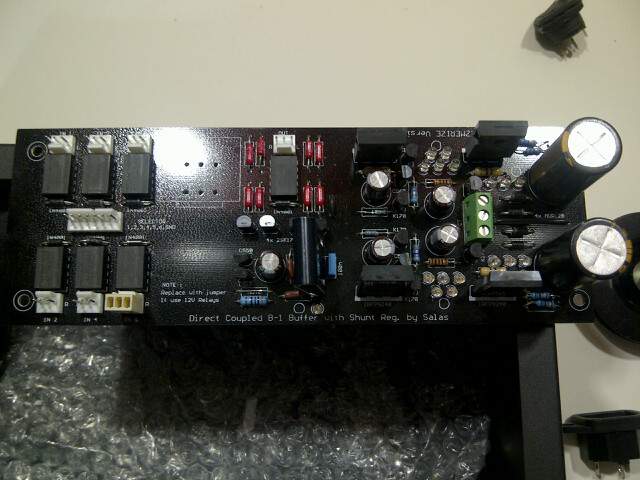
V in from off board prefilter + - 24V. Too high but I don't see any overheating problem. Mosfets are bolted on case.
I used 22R//22R per side and I measured +1.332 V and - 1.532 over them.
I think that that means 121 ma on + and 139 ma on -.
After regulation I get +10.11 and -9.46.
And last but not least -0.1/2/3 mV offset for one channel and 0.0/1/2 mv for the other . Could be true ?
For prefiltering I used an existing setup 2 x 0-20 50VA xformer and 2 x 2200 uF per rail. On board I have only a RC consisting of 22 R and 220 uF.
I haven't energize any input.
I'm writing these just to reconfirm that they cannot affect my measurements. Right ?
V in from off board prefilter + - 24V. Too high but I don't see any overheating problem. Mosfets are bolted on case.
I used 22R//22R per side and I measured +1.332 V and - 1.532 over them.
I think that that means 121 ma on + and 139 ma on -.
After regulation I get +10.11 and -9.46.
And last but not least -0.1/2/3 mV offset for one channel and 0.0/1/2 mv for the other
. Could be true ?For prefiltering I used an existing setup 2 x 0-20 50VA xformer and 2 x 2200 uF per rail. On board I have only a RC consisting of 22 R and 220 uF.
I haven't energize any input.
I'm writing these just to reconfirm that they cannot affect my measurements. Right ?
As I can understand from the schematic the input selector closes the circuit for the selected source so that relay is energized and conduct. Jump erring position 1 and ground (the two outermost holes of selector's holes block) on the board closes the circuit and energizes input 1. Right ?
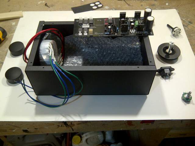
Listening ...
Dangerously hooked up to the system it plays good music... I suspect tiding up the whole thing (enclosure, proper wiring, proper psu, hotter robing, ..) will make it sound even better.
Finally 2sk170 is a wonderful tube
Thanks god there is no "fet rolling" ...
Salas and all, I kept my big thank for your help until listening to the first notes..
Thanks
Back then Panasonic TQ2 5/12 and Omron G6H DC12 were much around. The NEC EA2 5 or 12 is also compatible and presently seen online. A couple of members were offering relays and leds regularly also. All those types and makes mentioned are best quality, that is why we used them. I don't think that there will be any special issue for old black board, more than careful assembly not to need exchanging parts a lot due to wrong orientation, its more sensitive as single sided board for lifting pads. Watch the leds orientation especially well. CCS current its your own choice as always but I don't recommend more that 200mA for the black board because of small diodes only, smaller dissipation space for Rset fewer big filter capacitors.
Help connecting Power and Selector Switch to Mezmerize
NOTE: I posted this over on Audicircle, but have yet to get the full answer
Hello Folks, I recently received a fully stocked Mezmerize Board and plan to put everything together in a case this weekend, however I have a few questions that I know you good people can easily answer.
Wiring the Antek transformer to 110V
I have 2 Black and 2 Red wires to connect to the 110V IEC, so do both pairs need to be connected, or just one. Does it matter which wires are connected where? No ground wire is used?
Powering the Mezmerize Board with the Antek Tran 12V
Again, I have 2 Green and 2 Blue wires coming out of the transformer, how exactly do these connect to the Mesmerize Board?
Selector Switch to inputs on Mezmerize Board
Included in the bundle, was an Alpha 7M4 Selector Switch. I understand this Selector Switch connects to the boards Selector Pins and Ground, but again I am confused how this is to be wired. Any assistance/explanation as exactly how this is done would be greatly appreciated as I’m a bit/very confused.
I believe the rest is pretty straight forward, and don’t foresee any issues, however I do have a few questions, that I wouldn’t mind getting answered.
Is the Selector Switch actually in the signal path, or on the Mezmerize board is it purpose simply to engage the correct relay/input. Curious?
I plan to run an output for a Sub, in addition to an out to the Amp. No problems in doing this? And is as easy as taping a second set of RCAs of the first set of outputs?
I think that’s all my questions for now.
Again, I realize these are very simply questions, but want to avoid screw ups, and do it right the first time.
Thanx in advance for your input, Fred in Canada
Is there an easy to follow guide for component swaps for hot rodding the 'blue' mezmerize board ?
Ta....
Not really a guide needed. Just use 10 Ohm 3-5W setting resistors and bolt the Mosfets to the case or to a sink, using insulation pads.
Fredly:
Regarding the switch, no it isn't in the signal path. It just energizes the relays. You just connect a row of its pins to 1,2,3,4,5,6 as depicted on board and their respective ''output'' pole pin to GND.
Regarding an output split, better put 100R in line with the ''hot'' RCA pins of the extra output, its buffering it better.
As for the Antek, someone who used that particular trafo may reply you the wire colors, but some communication with the company would give answers too I suppose. For its secondary side you need to know which colors are making a center tap. Those are going to the center screw of the green connector, the others to the side screws.
- Home
- Amplifiers
- Pass Labs
- Mezmerize DCB1 Building Thread