There's 30-35Ω internal JFET resistance plus the 220Ω output resistor. Creating around 250Ω Zout in a standard DCB1.
Its for driving cable capacitance without disturbing the active circuit and helps survive output signal line shorts. Proved a universally stable choice. Too much resistance softens the sound nonetheless. I don't recommend increasing it unless there's an oscillation whine or harshness with some amplifier or powered monitors and long signal cables.
You can aswell progressively reduce that resistor's value for little more impactful sound as long as no problems are produced in a given system. Remember to add the JFET's intrinsic resistance when doing Zout to Zin calculations for driving an amplifier or any other gear or for when interfacing to a transformer.
Yes, it refers to the 220R output resistor. Was 1k in the original capacitor coupled B1 and I reduced it to a point that it was still safe for general use. The 1Meg is just a local reference to output ground and it is inconsequential as it is. It has high value not to change the following gear's input impedance because it stands in parallel. The moment you connect an amp or active speaker etc. to the DCB1's output the 1Meg leaves the picture. In any case that resistor shall not be reduced too much because at a point it will create additional loading stealing output driving current.
Pass DIY Addict
Joined 2000
Paid Member
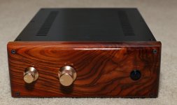
I've had this "built" and somewhat usable for several years now. Three and a half years ago, I mounted the boards in this chassis, but never put a face plate on it. The regulator mosfets are mounted to the chassis floor and I've used 6.5w 4R resistors to bias the DCB1 regulator. So, here it is, finally finished.
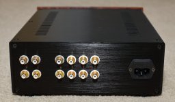
It's got four inputs and dual outputs, with outputs separated by 100R. The volume control is a matched set of LDRs that I picked up from Uriah ages ago, and they're driven by one of Salas' nice 5v shunt regulators. The front panel is piece of Cocobolo that I picked up several years ago and finished with some Formby's Tung Oil Finish. Now my only challenge is finding those little screws that hold the top plate in place - can't remember where they went ...
...
It's got four inputs and dual outputs, with outputs separated by 100R. The volume control is a matched set of LDRs that I picked up from Uriah ages ago, and they're driven by one of Salas' nice 5v shunt regulators. The front panel is piece of Cocobolo that I picked up several years ago and finished with some Formby's Tung Oil Finish. Now my only challenge is finding those little screws that hold the top plate in place - can't remember where they went
...Attachments
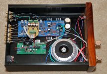
Congratulations! A really nice medium form factor build with an aesthetically pleasing thick wood panel of rich grain. Very good components inside too like Vishay foil resistors in the signal path. Wiring is single strand silver?
By the way LDR volume controls owe to add enough second harmonic holding back from the 0.001% THD+N DCB1 is capable of but subjectively many people like LDR.
By the way LDR volume controls owe to add enough second harmonic holding back from the 0.001% THD+N DCB1 is capable of but subjectively many people like LDR.
Pass DIY Addict
Joined 2000
Paid Member
I am sure it does. What amp and speakers are you currently using with it?it sounds quite nice!
Pass DIY Addict
Joined 2000
Paid Member
At present, it's sitting before my 300B mono amps and driving a set of 40L Tang Band 1778 speakers. Those speakers need a little help, so I picked up one of Nelson's single driver EQ boards, but haven't populated it yet. What I'd like to do with it shortly is to put it ahead of Zen's SissySIT amp and drive my Tony Gee Calpamos speakers with it. It takes a little effort to move things in and out of the playback chain...
Hi Salas,There's 30-35Ω internal JFET resistance plus the 220Ω output resistor. Creating around 250Ω Zout in a standard DCB1.
Its for driving cable capacitance without disturbing the active circuit and helps survive output signal line shorts. Proved a universally stable choice. Too much resistance softens the sound nonetheless. I don't recommend increasing it unless there's an oscillation whine or harshness with some amplifier or powered monitors and long signal cables.
You can aswell progressively reduce that resistor's value for little more impactful sound as long as no problems are produced in a given system. Remember to add the JFET's intrinsic resistance when doing Zout to Zin calculations for driving an amplifier or any other gear or for when interfacing to a transformer.
I have been experimenting as per your suggestion with the 220r resistor. It sounds absolutely great without any resistor and creates no other issues in my setup. I am following this with a Slagle AVC.
Could you please tell me what happens if one accidentally shorts the output to G in a setup which has no output resistor? Do the 2SK170 immediately destruct? Will that result in no sound at all or a distorted sound?
Thanks as always for sharing your experience and knowledge.
Nash
Hi, the output resistor is mainly there to provide damping against possible oscillations with the interconnects and driven equipment. But it also acts as a current limiter. In case of an output short to ground without such a resistor and no signal at the time, only Idss will run from output to ground. If there's signal, some negative going strong current bursts will go through the top Jfet to ground that may destroy it. Especially if there is signal with higher peak than Vgs (off). Say more than 0.5V peak content or some strong transient noise due to making hasty live connections. But even a small value output resistor like 10R can go a long way saving the day in case of a hard output short and not too high a signal.
I have found destroyed jfet in the output stage of a friend's ufsp phono after he did live interconnect swap with different ground potential gear and the sound just ceased. Its a similar buffer but in single polarity supply. In that case there's no output resistor but there's an output capacitor.
Good morning!
I am again sitting at my DCB1") , finalizing it and adding what might be needed: A second output to be able to hook it into other systems. (I have at some point decided to connect my builds with non-standard Lemo/Nim-Camac. Like it a lot, but it comes with a price.) These will be used as either this or that, no intend to use both. Should I make a switch, or is the 100r to the second plug sufficient? (As I am not sure wether the resistor would have an impact of sorts?)
, finalizing it and adding what might be needed: A second output to be able to hook it into other systems. (I have at some point decided to connect my builds with non-standard Lemo/Nim-Camac. Like it a lot, but it comes with a price.) These will be used as either this or that, no intend to use both. Should I make a switch, or is the 100r to the second plug sufficient? (As I am not sure wether the resistor would have an impact of sorts?)
Thank you so much!
d.)
I am again sitting at my DCB1
, finalizing it and adding what might be needed: A second output to be able to hook it into other systems. (I have at some point decided to connect my builds with non-standard Lemo/Nim-Camac. Like it a lot, but it comes with a price.) These will be used as either this or that, no intend to use both. Should I make a switch, or is the 100r to the second plug sufficient? (As I am not sure wether the resistor would have an impact of sorts?)Thank you so much!
d.)
A switch, if handy to you, is real insulating solution vs buffering resistors especially if it switches grounds too. So the outputs hooked equipment don't interact via their Zinputs and cables at all. And you also avoid the extra output impedance from additional resistors of course.
Another question to which I haven't seen anything: This seems to be the rare thread where barely anyone is mentioning ground-connection to the chassis. Am I correct to assume I should connect it to the chassis through a ground-lifter (as you once mentioned through a network of diode/cap/resistor)?
Thanks again!
Thanks again!
- Home
- Amplifiers
- Pass Labs
- Mezmerize DCB1 Building Thread