Nelson Pass said:And if you put instant coffee in a microwave oven, you will
go back in time.
")
Nelson Pass said:And if you put instant coffee in a microwave oven, you will
go back in time.
They dont have Senseo's yet in california ?
Looks like espresso, doesnt even taste like coffee !
jacco vermeulen said:They dont have Senseo's yet in california ?
Looks like espresso, doesnt even taste like coffee !
Ersatz Bros. coffee, the real one.
Nelson Pass said:And if you put instant coffee in a microwave oven, you will
go back in time.
Harrgh! that's funny.......timing is everything.
Cheers.....

Nelson Pass said:That's a joke, son.....
Foghorn Leghorn
"As about as sharp as a bowling ball"
jneutron :
You were neglecting the spreading effects of the own heatsink. Note that an aluminum heatsink and a BeO2 insulator have similar thermal conductivities so there is no advantage in making the BeO2 sleeve thicker
In the other hand, copper has almost twice the thermal conductivity of aluminum, so a copper heat spreader of *optimum* heighth, width and depth would achive the lowest thermal resistance. Optimum size calculation depends on heatsink geometry and a bigger than optimum one hurts perfomance instead of improving it
John,
you must know what the exact square area of the TO3 base sink is ?
I use AL2O3 TO3 insulators, in your list it is mentioned with a Tr of 0.94.
Any idea what Tr for Mica is ?
Once again i am pleased to read the factor 2 to 10 degrees rule !
I am storing your postings in a pdf, as i do with NP talk, joke or otherwise.
Now i need to find that coffee brand, a good thing that i speak German !
Thank you.
jacco.
Eva said:Optimum size calculation depends on heatsink geometry and a bigger than optimum one hurts perfomance instead of improving it
Eva,
you mean that Tr rises because of the added thickness ?
Simplified : if the height were x, and width at the top b, then
d[ x/ (b+2x)2 ]= 0 needs to be calculated ?
(supposing square dimensioning)
Eva said:jneutron :
You were neglecting the spreading effects of the own heatsink. Note that an aluminum heatsink and a BeO2 insulator have similar thermal conductivities so there is no advantage in making the BeO2 sleeve thicker
Cool, you really do know this stuff...nice..
You are absolutely right. I was showing conceptually, how the spreader internal to the package, makes better use of the package to heatsink interface when the interface is a lousy thermal (relatively) conductor. It's counterintuitive, as most would think that bringing the die closer to the heatsink helps the die run cooler..that is only the case if the package to heatsink interface is a very good conductor.
Eva said:In the other hand, copper has almost twice the thermal conductivity of aluminum, so a copper heat spreader of *optimum* heighth, width and depth would achive the lowest thermal resistance. Optimum size calculation depends on heatsink geometry and a bigger than optimum one hurts perfomance instead of improving it
Yah....you know this stuff well...it's a pleasure..
For these calcs, the heatsink geometry doesn't come into play, I'm only considering a constant heat flux, and power density.
The spreader, by definition, should be used to lower the power density at the interface which has the poorest heat conductivity.
Cheers, John
jacco vermeulen said:John,
you must know what the exact square area of the TO3 base sink is ?
I use AL2O3 TO3 insulators, in your list it is mentioned with a Tr of 0.94.
Any idea what Tr for Mica is ?
When the chip is small, and the case thin, the alumina will only be really effective under the die plus that 45 degree cone. If you calculate the thermal resistance by using the entire footprint of the alumina, the number will be much lower than reality, because most of the heat is coming out based on that 45 degree cone, not the entire package bottom.
The polymer type insulators have lower conductivity, so the entire package gets hotter, and the entire insulator is used. So, the device will run hotter, but the area-resistance calc will be closer to footprint, not 45 cone..and it will be less susceptible to mounting issues, where the alumina is..
Found the mica data here, but units are different from what I use..
http://www.frostytech.com/articleview.cfm?articleID=233
Copper has conductivity of 398 W/M-K..mica .7, so copper is 568 times more conductive..since copper is 10.2 W/inch-C, mica is 10.2/568, or .017 w/inch-C.
Cheers, John
jacco vermeulen said:
Eva,
you mean that Tr rises because of the added thickness ?
Simplified : if the height were x, and width at the top b, then
d[ x/ (b+2x)2 ]= 0 needs to be calculated ?
(supposing square dimensioning)
Yes, that's what she means..
As the spreader gets thicker and thicker, the cone will eventually hit the sides of the bottom of the spreader. That is the most it will spread based on the model...so, if you keep on making the spreader thicker, all you are doing is adding more copper with it's thermal resistance, but you are not making the contact to the case any wider...so if the spreader is a foot high, you'll see the thermal drop of a foot of copper..
Cheers, John
Re: Hello
I came into the pic very late here, so did not see the origional question..
Thermally, the TO-3 package will most likely have an advantage with respect to heatsink attach, the old two hole vs one..
It may also have an advantage as a result of the available internal headroom, allowing the use of a heat spreader.
It may be worse, depending on the case material, as the thermal conductivity of copper tabs on the plastic ones is better. But, without a heat spreader because of height restriction, the TO could have better performance with lousy insulators, while a plastic with BeO will have major advantage.
As for actual thermal resistance numbers, this test can be significantly biased, based on where the thermocouple is placed on the device..
The hermetics generally are made with magnetic materials, and that can be an issue with high switching speeds.
But, both package cases are entirely useable in the thermal range for which the semiconductor will operate..
The transient thermal impedance will not be significantly different in the two packages, until the heat pulse reaches the insulator. The glob top on the die does not have sufficient heat capacity to affect transient thermal response.
As for your picture...I would not recommend operation of standard silicon at anywhere near 150 C. that is only asking for trouble. A reactive load will most certainly push the die temp over the edge, and boom..
As for the analytical stuff...sorry for subjecting you to that, but as a significant difference between the package styles is height and package material, which require an understanding of the analytical model to explain the variables, the discussion of analysis was necessary.
Cheers, John
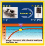
Workhorse said:Hi every body,
Is this discussion is really going on Plastic vs. Metal transistors or their type of analytical models in terms of thermal criteria.
how about this pic.
cheers,
Kanwar.
I came into the pic very late here, so did not see the origional question..
Is there any inherent advantage to using TO-3 packages vs their flat pack counterparts?
The only thing I can think of is a possible thermal advantage, with better case to heatsink or case to ambient cooling. Maybe junction to case as well, if the die bonding is better in a metal herm sealed package. But I can't find any numbers in the spec sheets to know for sure.
Thermally, the TO-3 package will most likely have an advantage with respect to heatsink attach, the old two hole vs one..
It may also have an advantage as a result of the available internal headroom, allowing the use of a heat spreader.
It may be worse, depending on the case material, as the thermal conductivity of copper tabs on the plastic ones is better. But, without a heat spreader because of height restriction, the TO could have better performance with lousy insulators, while a plastic with BeO will have major advantage.
As for actual thermal resistance numbers, this test can be significantly biased, based on where the thermocouple is placed on the device..
The hermetics generally are made with magnetic materials, and that can be an issue with high switching speeds.
But, both package cases are entirely useable in the thermal range for which the semiconductor will operate..
The transient thermal impedance will not be significantly different in the two packages, until the heat pulse reaches the insulator. The glob top on the die does not have sufficient heat capacity to affect transient thermal response.
As for your picture...I would not recommend operation of standard silicon at anywhere near 150 C. that is only asking for trouble. A reactive load will most certainly push the die temp over the edge, and boom..
As for the analytical stuff...sorry for subjecting you to that, but as a significant difference between the package styles is height and package material, which require an understanding of the analytical model to explain the variables, the discussion of analysis was necessary.
Cheers, John
jneutron...
To get more specific, what do you think is the reason for the disparity in manufacturers thermal specs for otherwise identical transistors in the different packages...I've been trying to wrap my mind around the differing specs for these on-semi parts:
mj21193-250w
mjl21193-200w
At 50w, 70c on the heatsink, say 100c on the die, the to3 would appear to have a huge advantage after derating. despite the fact that the dies are, by definition, at the same temp...there is something strange going on, and I don't totally discount lousy manufacturer docs...
Stuart
Re: jneutron...
The reason the metal is spec'd higher, is that the die is allowed to get up to 200 C, while the plastic is limited to 150.
Both have identical Rjc of .7 C/W..both are derated 1.43 Watts per degree C.
If you take that 1.43 watts per degree C, and multiply it by the 50 degrees hotter the TO can go, that is 71.5 watts more...so, the 250 watts seems conservative with respect to die temp..
I say seems, because if you cooled the case to -65 C, in theory you should be able to push 379 watts into the device before the die temp reached 200 C.. but, that's pushing the device much harder than designed..
So, the chip is designed for 250 watts dissipation, and the plastic case is limited by the material properties of the plastic itself.
They indicate that the dice themselves will behave identically, and reach the same working temperature..
Cheers, John
I checked moto and on semi datasheets..for all, the metal case is 250 watts, the plastic is 200watts.Stuart Easson said:To get more specific, what do you think is the reason for the disparity in manufacturers thermal specs for otherwise identical transistors in the different packages...I've been trying to wrap my mind around the differing specs for these on-semi parts:
mj21193-250w
mjl21193-200w
At 50w, 70c on the heatsink, say 100c on the die, the to3 would appear to have a huge advantage after derating. despite the fact that the dies are, by definition, at the same temp...there is something strange going on, and I don't totally discount lousy manufacturer docs...
Stuart
The reason the metal is spec'd higher, is that the die is allowed to get up to 200 C, while the plastic is limited to 150.
Both have identical Rjc of .7 C/W..both are derated 1.43 Watts per degree C.
If you take that 1.43 watts per degree C, and multiply it by the 50 degrees hotter the TO can go, that is 71.5 watts more...so, the 250 watts seems conservative with respect to die temp..
I say seems, because if you cooled the case to -65 C, in theory you should be able to push 379 watts into the device before the die temp reached 200 C.. but, that's pushing the device much harder than designed..
So, the chip is designed for 250 watts dissipation, and the plastic case is limited by the material properties of the plastic itself.
They indicate that the dice themselves will behave identically, and reach the same working temperature..
Cheers, John
whoops...my error..
Whoops...I had to correct that statement...
I'm showing my age here...back when dino's roamed the earth, there were no semi devices capable of 200 C operation..moto was just starting to "hint" about 175 C operation.
In looking at those 21193 specs, boy have those diffusion guys gotten better...wow..200 degrees...now, that's scary..
It doesn't change anything else, otherwise...both beasts are thermally identical..
Cheers, John
PS..guess that's what happens when ya get used to workin with silicon at 4.5 K, ya forget about the other end...
jneutron said:But, both package cases are entirely useable in the thermal range for which the semiconductor will operate..
Whoops...I had to correct that statement...
I'm showing my age here...back when dino's roamed the earth, there were no semi devices capable of 200 C operation..moto was just starting to "hint" about 175 C operation.
In looking at those 21193 specs, boy have those diffusion guys gotten better...wow..200 degrees...now, that's scary..
It doesn't change anything else, otherwise...both beasts are thermally identical..
Cheers, John
PS..guess that's what happens when ya get used to workin with silicon at 4.5 K, ya forget about the other end...
Someone needs to do some test on nominally identical devices in different packages with various mounting methods (direct, thin insulator, thick insulator, screws, clamping bar, clip). All that needs to be measured is the heatsink temperature, which will allow relative thermal conductivity die-to-heatsink to be calculated. No need for absolute measurements. I might do it if someone can suggest some suitable devices that are cheap.
Interestingly, Exicon do their MOSFETs in TO3, TO247 and TO264 cases. TO3 devices go up to 250W. Equivalent TO247 up to a mere 125W. TO264 up to 250W (same as TO3). Their datasheets say 1.0C/W juntion-to-case thermal resistance for all three packages, but I don't think I trust their numbers.
Interestingly, Exicon do their MOSFETs in TO3, TO247 and TO264 cases. TO3 devices go up to 250W. Equivalent TO247 up to a mere 125W. TO264 up to 250W (same as TO3). Their datasheets say 1.0C/W juntion-to-case thermal resistance for all three packages, but I don't think I trust their numbers.
- Status
- This old topic is closed. If you want to reopen this topic, contact a moderator using the "Report Post" button.
- Home
- Amplifiers
- Solid State
- metal vs plastic transistors