Yea, weak bass. Driving Kef Q1's. I was using an old NAD 7225 receiver, but it went "pop".
When I was setting the bias, I ran a spectrum plot. It was down by 2 dB at 20 Hz, -1 at 20K, so the perception of weak bass is kind of surprising. It is not at all taxed in my office. I am sure I am not using more than a few watts. Thinking about it, it may just be that the Kef's are just not very dynamic sounding. The more lively NAD may have helped them a tad. New office speakers are about 3 projects out, so I will know by then if I am staying glass or not.
What I know for sure, is I have GOT to clip those blue LED's out of there. Tacky! Lots of use for LED's in a tube amp, but making the base glow blue is not one of them.
Yea, weak bass. Driving Kef Q1's. I was using an old NAD 7225 receiver, but it went "pop".
When I was setting the bias, I ran a spectrum plot. It was down by 2 dB at 20 Hz, -1 at 20K, so the perception of weak bass is kind of surprising. It is not at all taxed in my office. I am sure I am not using more than a few watts. Thinking about it, it may just be that the Kef's are just not very dynamic sounding. The more lively NAD may have helped them a tad. New office speakers are about 3 projects out, so I will know by then if I am staying glass or not.
What I know for sure, is I have GOT to clip those blue LED's out of there. Tacky! Lots of use for LED's in a tube amp, but making the base glow blue is not one of them.
Did a bit of reading on this forum on the Q1's, and it seems as though they would sound a bit laid back with a tube amp. My speakers are somewhat on the larger side than the Q1's.
Swap those blue LEDs for orange ones for a little more warm tube glow

My amp doesn't have those anyway.
Gary, I am not using cathode bypass caps on the first stage. If all your voltages are similar to the schem I posted, I can only put the difference down to the input tubes I'm using, 6N1P vs Chinese 6N2. The 6N2's I had did not work very well in this cct, and gain was a bit low... The 6N1 draws more heater current than the 6N2 but the power tranny does not seem to mind so far (23% increase in current drawn from the windings).
tvr I need one of those Morgan Jones books too, should have bought one ages ago. Will order one ASAP. No lack of deep bass at this end. The LM317's, even though they are sometimes (or often) put down as a poor choice of component in this position, in my meagre experience they give good deep bass and nice sound, and in this cct, good current balance in the OPT's with one under each output tube, plus auto bias. Maybe in a few months or years I will look back and say, no, that is not the way to go, but until then...
tvr I need one of those Morgan Jones books too, should have bought one ages ago. Will order one ASAP. No lack of deep bass at this end. The LM317's, even though they are sometimes (or often) put down as a poor choice of component in this position, in my meagre experience they give good deep bass and nice sound, and in this cct, good current balance in the OPT's with one under each output tube, plus auto bias. Maybe in a few months or years I will look back and say, no, that is not the way to go, but until then...
I could not wait till the weekend, the voltage tripler got fitted, one diode and one 20uF 450V cap = 380V, have 300V at the input stage using 27K instead of 22K to the 33uF caps, so room to move. Sounds better again, even more clean i.e. more detail, and sweet. Run out of time to do any more.
It should be a hint: I bought both of Jones' books and the new Jung book. The amount of time discussing execution and not just circuit should be a big hint. The VTL book and even a lot of the old press comments on the PV-5 all support how important it is. So I have about 2000 pages to study.
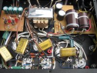
Meng Yue PCB
Time for a cleanup, thought this pic might be helpful to you guys for reference.
http://i198.photobucket.com/albums/aa160/birdy81260/MengYuePCB.jpg
Despite what I said earlier, I discovered 3 broken pads...
Execution? Have I missed something?
Time for a cleanup, thought this pic might be helpful to you guys for reference.
An externally hosted image should be here but it was not working when we last tested it.
http://i198.photobucket.com/albums/aa160/birdy81260/MengYuePCB.jpg
Despite what I said earlier, I discovered 3 broken pads...
Execution? Have I missed something?
Last edited:
What have we got here Svein? I see 2 x CCS I think, and a choke or extra B+ tranny, and it looks like no voltage doubler, maybe your amp did not use that originally? Thanks for sharing.
I was thinking of scrapping the PCB, or scraping off the tracks and fitting tag strips, but decided to rebuild it as I haven't decided the final schematic yet. I will move most of the power supply off board to reduce clutter, make it easier to work on.
I was thinking of scrapping the PCB, or scraping off the tracks and fitting tag strips, but decided to rebuild it as I haven't decided the final schematic yet. I will move most of the power supply off board to reduce clutter, make it easier to work on.
What have we got here Svein? I see 2 x CCS I think, and a choke or extra B+ tranny, and it looks like no voltage doubler, maybe your amp did not use that originally? Thanks for sharing.
Very observant!
I rebuilt the input stage to LTP with CCS, similar to the Baby-Huey.
The Yarland 34Ciil has a 200V PT with full-wave rectifier, and a PS chocke. Hence no doubler required.
Svein.
Ian, yes my amp has 6N2 as drivers. I managed to see the 2 in the bits of printing left on them. The voltages in mine are similar to your schematic.
If I can find a source of tagstrips I will probably p-2-p mine. Nobody over this side of the pond seems to stock them anymore.
Just received a bunch of Russian tubes to try so I'll let you know how it compares when I put 6N1P-EV in the front.
Gary
If I can find a source of tagstrips I will probably p-2-p mine. Nobody over this side of the pond seems to stock them anymore.
Just received a bunch of Russian tubes to try so I'll let you know how it compares when I put 6N1P-EV in the front.
Gary
Gary, try Jaycar for the tagstrips. If no joy I can send you some if you like.
Duh! I don't know why I didn't search Jaycar better. I looked under terminal strips and didn't see anything. Thanks for that.
Well, the 6n1ev certainly sound lots better, particularly at the hf end. Cymbals go tssshh now, not tzzzzz as they did before.
I was expecting the gain to drop further, as the mu is only 1/3 of the 6n2, but that isn't the case (going to have to study the relationship of gain to circuit values more). It actually seems higher. Might be able to pull the bypassing from the cathode now, or at least split the cathode resistor into two and implement some feedback.
I still have the Chinese 6P1's in the output stage, but I aim to try some Russian 6P1-EV in there for comparison.
It's a pity the 6P1 and 6P14/EL84 don't have the same pinout. I have a couple of NOS EL84's I would love to try.
Gary
I'm sticking with the 6P1 for now (vs EL84) since it is a different characteristic tube, beam tetrode vs pentode, just curious at this stage. The other consideration is heater winding power, adding EL84 will raise the total heater winding power from 20.2W to 26.7W with 6N1 driver tubes, or 16.4W to 22.7W if using 6N2 tubes. I rewired the heaters for 12AT7, but didn't like the sound, went back to 6N1P, with the extra voltage on the input tubes the sound quality exceeds any expectations I ever had. Will post a schem and voltages later.
front
underneath
modded PCB
front
underneath
modded PCB
Last edited:
Yes, I should move all the components to the same side of the PCB as well.
I was able to remove the cathode bypass from the first stage with the 6n1 tubes. No way with the 6n2 unless I wanted less than 1 watt full power out.
I have altered the cathode resistance of the first stage into 1k5 and 270 ohms in series so that I can experiment with feedback. I need to increase the damping factor a bit, as the bass is really undamped on my TL speakers. Connecting a feedback resistor of 22k from the speaker o/p direct to the cathode dropped the gain too much, especially at the LF end (no parallel capacitor on the 22k). I'll probably replace the 270 with a 500 ohm pot if I have one, just to settle on a FB value.
I tried the Russian 6P1-EV in place of the Chinese 6P1 in the output, but didn't notice much difference. I may notice more when the feedback issue is sorted.
Gary
Hi Gary, I changed the schematic a bit more towards the RLD design. I also ordered some LED's from Farnell to try the LED's on the output tube cathode as per the RLD design , also some voltage regulator parts for the screen grid supply. The RLD also has an RC network on the anode of the first input stage tube for feedback stability, worth a look , might give you some feedback ideas.
How did your 68R resistor on the input to the power tranny go? I am thinking of doing similar. Is 5W enough or better to use a 10W rating?
I didn't notice a lot of difference between the 6P1 and 6P1P either, but my wife preferred the 6P1P, which seemed to have a slightly stronger top end.
Ian.
How did your 68R resistor on the input to the power tranny go? I am thinking of doing similar. Is 5W enough or better to use a 10W rating?
I didn't notice a lot of difference between the 6P1 and 6P1P either, but my wife preferred the 6P1P, which seemed to have a slightly stronger top end.
Ian.
Funny you should mention the mains dropper, it just gave up a few minutes ago. I had it calculated max dissipation of 4W, but obviously not getting ventilation killed it. It had been REALLY HOTHi Gary, I changed the schematic a bit more towards the RLD design. I also ordered some LED's from Farnell to try the LED's on the output tube cathode as per the RLD design , also some voltage regulator parts for the screen grid supply. The RLD also has an RC network on the anode of the first input stage tube for feedback stability, worth a look , might give you some feedback ideas.
How did your 68R resistor on the input to the power tranny go? I am thinking of doing similar. Is 5W enough or better to use a 10W rating?
I didn't notice a lot of difference between the 6P1 and 6P1P either, but my wife preferred the 6P1P, which seemed to have a slightly stronger top end.
Ian.
I now have a couple of Dale 50W 30 ohms to stick in there. Now that's belt and braces
Just have to figure a nice way to mount them without drilling holes in the top panel.I had wondered about putting a couple of vent slots at the back of the transformer cover as well.
Gary
I just looked at your diagram and noticed the DC bias for the heaters. Something I hadn't thought about until I looked at Vkh at 100v in the datasheet. I take it you removed the 500R pots from the heater circuit. Did you notice any hum problem? Mine are still in circuit.
I was playing with feedback resistor values when the mains dropper gave up, so I haven't come to any conclusions which way to go there.
I looked at the RLD, but don't know if I want an amp that looks like a car brake light
Gary
I was playing with feedback resistor values when the mains dropper gave up, so I haven't come to any conclusions which way to go there.
I looked at the RLD, but don't know if I want an amp that looks like a car brake light
Gary
The 500R pots are gone. When I went with the voltage tripler to get more B+ at the input valve I had to add the heater bias. It was OK without the tripler at ~75V, but now its 135V at the splitter's cathode. I should have a cap on the voltage divider but hum is not an issue at the moment. Brake light? We will see...I am curious about this overload recovery scheme.
We will see...I am curious about this overload recovery scheme.The missus asked me why the sound was not quite as "lively" after the rebuild. I said I only changed 2 components (the anode and cathode resistors on the first valve stage). I changed them back, much better, I changed the schematic linked above to reflect what it is right now. Not the first time she has helped me out, she likes her music and has good ears. As long as the amp stays the same or gets better all is good but if it gets worse... 
Hum, yes there is a small amount if you put your head at the speaker, but she cannot hear it yet. Might look into it at some stage.
but if it gets worse... Hum, yes there is a small amount if you put your head at the speaker, but she cannot hear it yet. Might look into it at some stage.
Just looked at your new diagram and I think I see an error. Your heater bias is now connected to both heater windings of the power transformer, and the windings are shown as Ch1 and Ch2. I think that one winding is the pre-tubes of both channels and the other is the power tubes?
Did you actually mean to raise the heater potential of the power stage as well?
Gary
Did you actually mean to raise the heater potential of the power stage as well?
Gary
- Status
- This old topic is closed. If you want to reopen this topic, contact a moderator using the "Report Post" button.
- Home
- Amplifiers
- Tubes / Valves
- Meng Yue Mini schematic?