Ok heres what i came up with . With both driver boards in the amp it has Dc on the outputs. I take both driver boards out of the amp. I put 1 in and the amp powers up fine no problems. Then switch it to the other side and amp power up no problems. So i take it out set it aside then put the other one in . If i put it on 1 side it blows the outputs. Put it on the other side and it cause dc on the outputs and makes the relay squeal. So im guessing i have a bad driver board.
So i guess im gonna have to rebuild that board
So i guess im gonna have to rebuild that board
Perry,
With no driver boards in the amp and all of the outputs in it amp powers up fine and no DC on the outputs.
Then with all the outputs in the amp and 1 driver board the amp it powers up and no DC on outputs.
With all of the outputs in the amp and both Driver boards in the amp I get DC voltage on the outputs 62.5 volts.
So i swapped the driver board out and stuck one in from another Memphis amp same model and Get DC voltage back on the outputs.
Does this sound like i have a bad driver board In this amp?
If i plug in any of the driver boards to either socket i have no DC I do not have DC voltage until both of the boards are plugged in. With both driver boards plugged in And DC on the outputs it doesnt produce audio. All it does is throw a huge spark out of the speaker terminals and kick the amp into protection and when thats going on the amp will draw 60+ amps of current
Does the relay engage and remain engaged with only one board?
With no boards, do you see any PWM modulation on the 2-pin wire connectors near the driver boards?
When you stated that the amp had no DC on the outputs, was that on the tabs of the output transistors or on the speaker terminals?
With no boards, do you see any PWM modulation on the 2-pin wire connectors near the driver boards?
When you stated that the amp had no DC on the outputs, was that on the tabs of the output transistors or on the speaker terminals?
Not knowing doesn't make you stupid. No one can know everything.
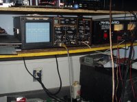
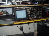
There are two 2-pin wire harnesses that send the PWM signal from the audio PWM driver board to the output driver boards. Remove the output driver boards and set your scope to 2v/div and 5uS (you may have to adjust those and the trigger level slightly to see the signal. Drive a strong audio signal into the amp and look for a PWM signal (square wave with varying pulse width - driven by the audio signal). Do you have a square wave (on the white wire, if I recall correctly)?
If you have only straight DC on the white wire, the black wire is at ground and there is no DC on the tabs of the output transistors, let me know.
It's an LM361.
Pull the IC and measure the voltages. That will tell us if you have the correct supply voltages on the IC.
Get some small heatshrink tubing to put on the probes. Only allow the very tip (a few thousandths of an inch) of the probe to remain uninsulated. That makes it very difficult to short between adjacent pins.
- Status
- This old topic is closed. If you want to reopen this topic, contact a moderator using the "Report Post" button.
- Home
- General Interest
- Car Audio
- Memphis 16-st1000d

