You heard it here first, only on diyaudio !
LD
Oh No! Burn in.
Oh No! Burn in.
I always thought the mechanism was a bit different, although I know from experience that most really expensive MCs improve with use during the first 50 - 100 hours, stabilize for a bit and then slowly deteriorate with use after that, unless the victim of an unfortunate accident. Sometimes a big dose of ennui induced by a particular cartridge assures it will never get worn out.. (Currently I don't have any of those.. )
IIIRC, there was a Japanese patent from back in the day for a record that re-polished a stylus. The record fitted onto a normal turntable, and had a single groove that swept a very slow sine shape, perhaps one or two cycles per revolution, between the inner and outer radius.And someone get down the patent office quick!
Can't seem to find it now, but IIRC it had a normal shaped groove cross section profile. Can't recall if it was normal vinyl or another material..............
Just that a pretty similar tracing shape, ie similar angles, would be obtained from a 300Hz@+12dB groove, and repetition rate would be far higher.........
LD
Hi. I had a weekend walk away and I missed the progress here.
Thanks Michael.
That’s a great tool. Is it for Android phones?
Lucky thank you for the service.
Impressive achievement of your method.
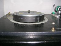
See attachment. The shim of a thermo-shrink around the sub platter.
It was a temporary installation in the mid of a mod to reduce the RPM of the platter (from +1.59% to –0.11%).
This is the only reason I spend time on the technicalities of vinyl playback
And thanks Bill for opening the new thread.
Ricardo I agree about the ADC.
But not about the test track (signal generator instability plus the instability of the cutting lathe).
See volken’s post here. Very telling
http://www.diyaudio.com/forums/analogue-source/309349-turntable-speed-stabilty.html#post5116465
I am amazed again of what the SW can achieve.
When you are ready for suggesting a new run of tests, I’ll put double sided adhesive tape btn the vinyl label and the mat and btn the mat and the platter.
I had a look.
There is a large number of Japanese patents on that, all around 1975-1982.
The polishing material was applied via vapor metalization over softer substrate
It was around the time the grooved video-disk read by a diamond stylus were introduced.
George
I forgot that I have the Platter Speed app on my phone.
Thanks Michael.
That’s a great tool. Is it for Android phones?
Here's two polar plots, one each for your TD160 + SME3009i + DL103, and the JVC QL-A2 +M97eX.
Lucky thank you for the service.
There's also a once per platter event at about 4 o'clock, which seems to have spectral content about 4Hz which might be warp, but doesn't show up when the same record was used on the JVC, so probably not.
Impressive achievement of your method.
See attachment. The shim of a thermo-shrink around the sub platter.
It was a temporary installation in the mid of a mod to reduce the RPM of the platter (from +1.59% to –0.11%).
But, be advised, there's a lot more myths waiting to be busted, which as we know isn't exactly ever popular.........
This is the only reason I spend time on the technicalities of vinyl playback
And thanks Bill for opening the new thread.
I doubt if the stability of the original tone or the ADCs are anywhere near the instability of vinyl playback.
Ricardo I agree about the ADC.
But not about the test track (signal generator instability plus the instability of the cutting lathe).
See volken’s post here. Very telling
http://www.diyaudio.com/forums/analogue-source/309349-turntable-speed-stabilty.html#post5116465
but drifted as to phase of polar speed variation around the platter in the course of the 150 plays.
I am amazed again of what the SW can achieve.
When you are ready for suggesting a new run of tests, I’ll put double sided adhesive tape btn the vinyl label and the mat and btn the mat and the platter.
IIIRC, there was a Japanese patent from back in the day for a record that re-polished a stylus
I had a look.
There is a large number of Japanese patents on that, all around 1975-1982.
The polishing material was applied via vapor metalization over softer substrate
It was around the time the grooved video-disk read by a diamond stylus were introduced.
George
Attachments
But not about the test track (signal generator instability plus the instability of the cutting lathe).
I wonder if 3150 Hz was chosen because there are exactly 1750 cycles in one revolution at 33 1/3 RPM. This way one could lock the oscillator to the lathe.
Most of the test records I have make perfect patterns in glancing light and appear in lock step groove to groove under a microscope. This is good for non-uniform rotation, I suppose a precision rotary index table and microscope could be used to check one groove once around.
I wonder if 3150 Hz was chosen because there are exactly 1750 cycles in one revolution at 33 1/3 RPM. This way one could lock the oscillator to the lathe.
Maybe.
Btw, I found this. The sw works on the input of the soundcard.
w&f measuring sw
https://www.lathetrolls.com/viewtopic.php?t=6002&p=37398
Most of the test records I have make perfect patterns in glancing light and appear in lock step groove to groove under a microscope.
I’ve heard so much about the test method using light pattern… (internet search is a marvelous thing, one day I have to read these)
http://www.extra.research.philips.com/hera/people/aarts/_Philips%20Bound%20Archive/PTechReview/PTechReview-23-1961_62-089.pdf
http://www.collinsaudio.com/Prosound_Workshop/BBC_%20LP_Light_Pattern.pdf
George
I’ve heard so much about the test method using light pattern… (internet search is a marvelous thing, one day I have to read these)
George
You can't see the 3 kHz tracks easily, but the 120 Hz strobe track on my STR 151 is perfect by eye start to finish, not the slightest phase slippage visible. Typical repeat plays of this would slip 2 or 3 cycles in this time. Statistically you should be able to use one radial row to get an estimate of short term variance of the cutter.
Last edited:
The NAB spec limit for record recording pitch tolerance for all effects up to 200Hz modulation bandwidth is +/- 0.04%, and I imagine healthy lathes do better than that.You can't see the 3 kHz tracks easily, but the 120 Hz strobe track on my STR 151 is perfect by eye start to finish, not the slightest phase slippage visible. Typical repeat plays of this would slip 2 or 3 cycles in this time. Statistically you should be able to use one radial row to get an estimate of short term variance of the cutter.
At that spec limit, a perfect playback polar plot would fit within a pair of tramlines, said to be beyond the limit of audibility.
LD
Last edited:
I must have missed the original explanation of your method. Any links to this? This pseudo DSP guru is very interested as it appears to have a novel relationship between FFT size, frequency resolution & time resolution.I genuinely detect very precise frequency, about 1 or 2 ppm measured on synthetic tones IIRC, and necessarily must use short FFTs for good time resolution.
There's a cute way of doing this which any FFT guru will surely already know..........
It's quite possible that (as I kunt reed en rite) I might have misunderstood you completely.
AM, Narrow Band FM & Narrow Band PM have very similar looking 'energy' spectrums. In fact the 'only' difference is in the phase of the sidebands.The spectrum inset graph is genuinely simply an FFT of FM demodulated deviation: the spectrum of whatever is FM modulating the test tone.
A few pages back the question was asked over whether ortofon ever used tie wires on their MMs. I can now confirm that they did in the hifi concorde/LM era. I know this as just discovered that the concorde10 that I bought on a whim is busted. The rear cover was broken off and I can see the remains of the tie wire on it. It also means I have an unusable body so will see if the generator can be removed without smashing it as with a modern OM body in could be quite fun.
Yes, it's cute.I must have missed the original explanation of your method. Any links to this? This pseudo DSP guru is very interested as it appears to have a novel relationship between FFT size, frequency resolution & time resolution.
There are at least two standard methods that are reasonably accurate, but both omit a key trick that significantly enhances accuracy and reduces variance here. The Boashash paper linked by Scott in post #5 of the Turntable Speed Stabilty thread sets out good theory, and answers your question in principle.
The method I use is my own (enhanced) version of one the standards, and in this situation it performs stunningly well.
I re-checked: for a synthetic 3kHz tone, measured absolute accuracy over a revolution is 0.16 ppm (0.000016%) and 5ms sample-sample sigma is 8.8 ppm (0.00088%) (!!!)
This performs insanely well, all using short ffts, and I don't intend to disclose the exact method. The concepts are well known and explained, (and well buried I might add!) within the Boashash paper and elsewhere, but there's a cute extra trick available in this situation that really pays back.
LD
Last edited:
Slightly OT. Does anyone have a copy of the 1954 Decca Messiah conducted by Sir Adrian Boult? I just aquired this out a skip, and despite being click and pop free has awful distortion on highly modulated passages. Now unless my cartridge has gone for a burton in the last week this suggests it has been played with 2'6d glued onto the headshell at some point in the last 50 odd years so would be a good candidate for testing the extreme stylus profiles I have waiting in the wings as opposed to my faithful elliptical.
Is that LXT 2921 thru LXT 2924 ? If so, should be fine and Decca were just revving up the fffr program and the underlying recordings were great and getting better......Slightly OT. Does anyone have a copy of the 1954 Decca Messiah conducted by Sir Adrian Boult? I just aquired this out a skip, and despite being click and pop free has awful distortion on highly modulated passages. Now unless my cartridge has gone for a burton in the last week this suggests it has been played with 2'6d glued onto the headshell at some point in the last 50 odd years so would be a good candidate for testing the extreme stylus profiles I have waiting in the wings as opposed to my faithful elliptical.
What colour are the labels, and what colour is the lettering on the labels, and what are the matrix numbers, and numbers letter at 3 and 9 o'clock ?
I haven't got that one (I think....?)
LD
Interesting. I hadn't found the original references, as mine are the ace of clubs issue, which are usually off the same stampers, but in this case the original was 4 LPs and the ace of clubs was 3, so a recut. As zero cost not worried if they are gash, but interesting for research purposes. This is where having a SEM to hand would be useful!
- Home
- Source & Line
- Analogue Source
- mechanical resonance in MMs