For hair splitting and FFT consider this- The FFT is a snapshot of the wave. The snapshot is used to generate a direct transform into the frequency bins. Several well recognized mathematicians, such as R. Hyser and others, warned strongly against using direct transforms as the results may or may not be accurate. It is far better to use statistical mapping which is always correct.
As for speakers transducers IMD leads to FM modulation. FM side products are by far the easiest to hear. This has recently been proved in the warning alarm industry which resulted in backup warning alarms using sweeping noise tones instead of "beep beep." Audibility is much higher in noisy unknown environments. Any kind of FM or non-harmonic signals are extremely easy to hear compared to variations in harmonic structures of time or magnitude of the harmonic. Consider it this way, in harmonic variation it is the same signal with slight variations in tones which probably already exist in the original music content. With non-harmonic tones being generated there are frequencies which did not exist in the original content. These tones are very easy to hear. Electronics can generate frequencies not in the original content by many methods. Speakers can by a much more restrictive set of conditions as gedlee suggest. Paul Klipsh wrote a very funny paper about that for speakers. Many have written about this in electronic circuits from TIM to instantaneous overload to foldback distortion in A/D D/A and on and on. A lot more discussion than solutions.
For added info check out the AES papers by D Preis on linear distortion. A landmark work in my opinion.
There has been a lot mnore work done on the perception of nonlinearities since Pries. See Perception for example.
Having considerable expertise in "Statistical Signal Processing", your alluding to its being "far better" is curious. It's different, but its still limited by the fundamental uncertanties of looking at a finite amount of data. Nothing gets past that problem. I have found that "in the end" they all give about the same results - "the answer", if done correctly.
Having considerable expertise in "Statistical Signal Processing", your alluding to its being "far better" is curious. It's different, but its still limited by the fundamental uncertanties of looking at a finite amount of data. Nothing gets past that problem. I have found that "in the end" they all give about the same results - "the answer", if done correctly.
One nice thing about statistical mapping is the sample set does not need to be a snapshot. The sample length can become very long allowing the mapping to become very accurate. Also there are no "synchronization" issues with statistical mapping.
I must agree though, to someone with lots of knowledge bogus data kind of stands out and can likewise be thrown out. As example, when I see a frequency response curve from a cone loudspeaker which has the appearance of a line from a ruler I know there was far to much integration or smoothing of the data.
Every test can have good data or bad data. Good mapping tends toward good data only which was my point. For testing in a box and not a custom device built on a DSP I really like this one: http://www.audiocontrol.com/t37/5650/19940/Acoustic-Analyzers/Acoustic-Analyzer-Iasysreg.html Lots of papers to read there also. This means anyone can use this device and often get good results without the expertise so few have.
One nice thing about statistical mapping is the sample set does not need to be a snapshot.
Would you care to explain this. What is meant by "statistical mapping" and "snapshot"? In Acoustic signal processing all data is sampled, in time, it's not a "snapshot", that would be a single sample. Can't get much information from that. Regardless of whether or not "statistics" is used in the processing the underlying data set is the same.
Please see the paper Random Noise Correlation for Delay Measurement at the link provided for Audio Control to see one example of statistical mapping use.
Snap shop refers to impulse testing using FFT where frequency and time data are directly transformed from the impulse. There are many issue with this. It is very useful for minimum phase systems, like electronics, but speakers are often more complex with bands of minimum phase and bands of unruly behavior which results in unreliable test data.
As this is not the place to define such subject please refer to this link:
statistical mapping site:aes.org - Google Search
As gedlee has stated there are many ways to measure loudspeakers. Adding to that, if a given loudspeaker measures well on all systems then there is grouping and statistical information which may correlate to a loudspeaker that works fairly well. On the other hand if a loudspeaker measures well on one system only and poorly on other test systems then there is a good chance that speaker is not so good. Single method validation is the marketing departments dream, hence the huge focus on "watt" in audio amplifiers! I believe you understand the point.
As a broad statement, a perfect speaker will measure pretty well on all systems based in well reasoned measurement methods. This is why so many different methods are used here and why, IMO we who are diligent have the option to use so many different methods. "Oh look, it is a great speaker!! Wait, look at this test... there is a real problem there*!*" Reality raises its' ugly head. So we continue to try and hopefully improve.
Those who focus on a very small set of testing or even the dreaded single test method will end making speakers which work well on the small set or single test. Those who use many test will see that every speaker has many flaws and will eventually order the test and make decisions about what is most important. gedlee finds constant directivity very important and I tend to agree. I find having all signals in phase is very important. I hate interference crossovers where drivers are operated out of 0, or near zero, phase with one another. Linkwitz wrote the original paper about keeping the main lobe of radiation pointed in the same direction through the crossover region. And here is a bunch of these: linkwitz lobe tilt site:aes.org - Google Search
The big trick to me is to make that magic speaker that does well on the many test setups. To me, that is the one on the left. Wish I had a pair...another custom install, oh well. maybe I do not charge enough.")
=SUM
Snap shop refers to impulse testing using FFT where frequency and time data are directly transformed from the impulse. There are many issue with this. It is very useful for minimum phase systems, like electronics, but speakers are often more complex with bands of minimum phase and bands of unruly behavior which results in unreliable test data.
As this is not the place to define such subject please refer to this link:
statistical mapping site:aes.org - Google Search
As gedlee has stated there are many ways to measure loudspeakers. Adding to that, if a given loudspeaker measures well on all systems then there is grouping and statistical information which may correlate to a loudspeaker that works fairly well. On the other hand if a loudspeaker measures well on one system only and poorly on other test systems then there is a good chance that speaker is not so good. Single method validation is the marketing departments dream, hence the huge focus on "watt" in audio amplifiers! I believe you understand the point.
As a broad statement, a perfect speaker will measure pretty well on all systems based in well reasoned measurement methods. This is why so many different methods are used here and why, IMO we who are diligent have the option to use so many different methods. "Oh look, it is a great speaker!! Wait, look at this test... there is a real problem there*!*" Reality raises its' ugly head. So we continue to try and hopefully improve.
Those who focus on a very small set of testing or even the dreaded single test method will end making speakers which work well on the small set or single test. Those who use many test will see that every speaker has many flaws and will eventually order the test and make decisions about what is most important. gedlee finds constant directivity very important and I tend to agree. I find having all signals in phase is very important. I hate interference crossovers where drivers are operated out of 0, or near zero, phase with one another. Linkwitz wrote the original paper about keeping the main lobe of radiation pointed in the same direction through the crossover region. And here is a bunch of these: linkwitz lobe tilt site:aes.org - Google Search
The big trick to me is to make that magic speaker that does well on the many test setups. To me, that is the one on the left. Wish I had a pair...another custom install, oh well. maybe I do not charge enough.
=SUM
Last edited:
=SUM,
I agree that one system metric isn't enough. The single FR graph commonly posted in product literature of the past never told us anything about their sound. Neither did their efficiency rating. It's just not enough info.
Have you seen this:
Table of Contents
I think we need to weight the metric according to their their audibility and make the most audible top priority. Making something that measures well in any metric that is demonstrated to be inaudible seems of little value to me. I don't want to focus long and hard on perfecting something that's been demonstrated to be unimportant.
What I'd love to see a list of is what parameters are most audible in order from most to least. That would be ideal to me but to set up the controls for that is beyond my expertise to say the least and to say I know that would be a lie. I do know that polar response is immensely important as is bass response and efficiency.
Any of you guys care to post such a list based on evidence and perhaps a bit of personal experience?
Dan
Last edited:
Snap shop refers to impulse testing using FFT where frequency and time data are directly transformed from the impulse. There are many issue with this. It is very useful for minimum phase systems, like electronics, but speakers are often more complex with bands of minimum phase and bands of unruly behavior which results in unreliable test data.
Are you saying that impulse-FFT systems do not detect minimum phase (or excess phase) accurately? I would strongly disagree with that. And so would anyone who has used an impulse FFT system to measure phase and done the phase-unwrapping to extract excess phase.
And are you saying that because an impulse represents one particular time sample that the overall behavior of the system is not accurately captured? If so, again strong disagreement- the autocorrelation of an MLS yields a time domain function whose FFT is identical to that of an impulse.
SUM= Your references have nothing to do with the topic at hand. I think that you are running me arround on a topic that you actually know nothing about.
Dan - if you read my works you will see my listing of importance. Its not new.
I'll be gone for a few days - later.
I know what's important to you, and I bet I could even guess as to the order of the list. It would just be cool to actually see it spelled out from top to bottom. That goes for other designers as well.
Last edited:
I'm a sucker for measurement data, point me to it and I will most certainly ask for more....
The big trick to me is to make that magic speaker that does well on the many test setups. To me, that is the one on the left. Wish I had a pair...another custom install, oh well. maybe I do not charge enough.
=SUM
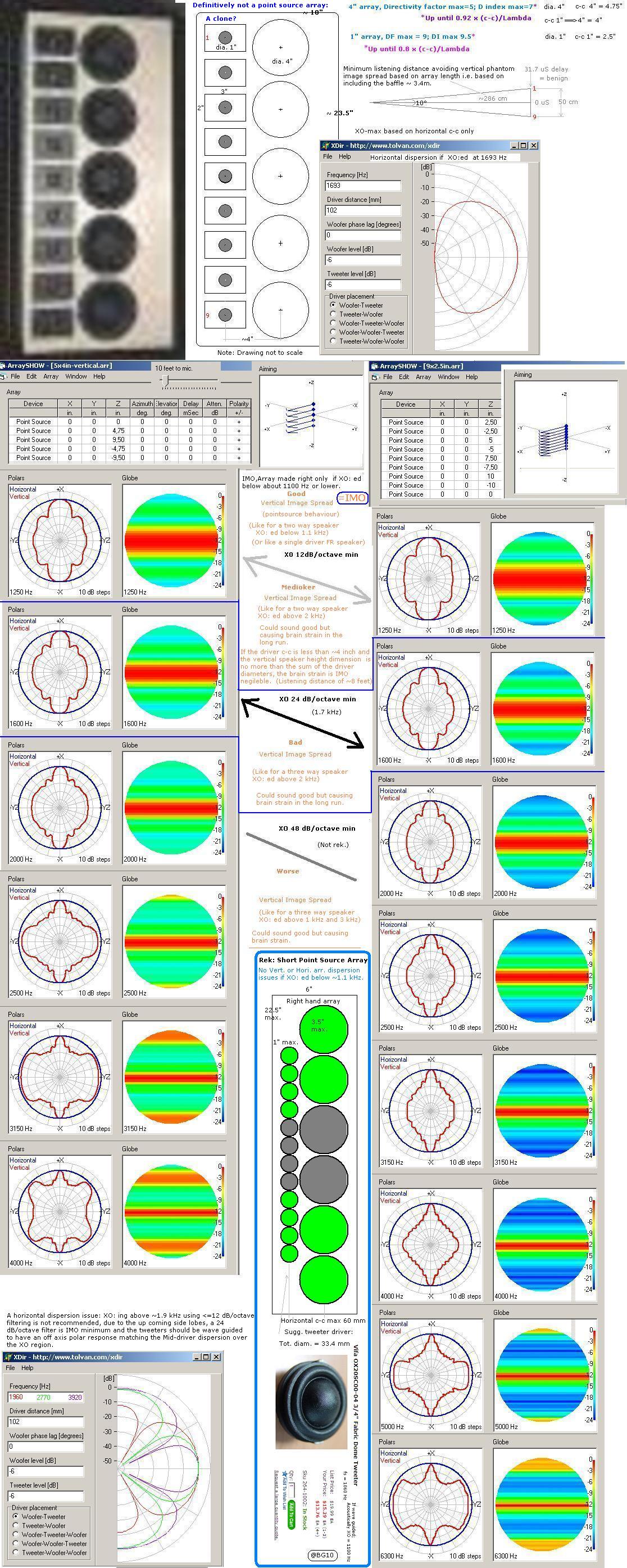
 He probably meant this magical design using ‘methods similar to "synthetic aperture" radar antenna systems’ ..SAR?
 Found here:
http://www.diyaudio.com/forums/mult...th-transducers-line-arrays-2.html#post2173098
..
 scrutinized here:
http://www.diyaudio.com/forums/atta...transducers-line-arrays-avatar-test-clone.jpg
b
Last edited:
Found here:
http://www.diyaudio.com/forums/mult...th-transducers-line-arrays-2.html#post2173098
..
http://www.diyaudio.com/forums/atta...transducers-line-arrays-avatar-test-clone.jpg
b
Yes that is correct and responded to here post #19 http://www.diyaudio.com/forums/mult...th-transducers-line-arrays-2.html#post2173098
I am certainly not saying FFT and impulse testing is not useful and not sometimes valid. R. Heyser warned of issue with direct transformation of such. Maybe I can find the reference and post a link. Sometimes it works especially in minimum phase systems and sometimes it leads to faulty data. Not dissing it entirely at all however it is another tool and not the only tool and as all tools subject to error. Does anyone here know of any test not subject to errors? Re can be determined accurately.
To measure phase response the time, the excess delay time, within the measurement system must be determined. The IASYS has a statistical method of determining this with the links and references I provided. Delay information is critical to anything to do with phase so I have no idea why anyone would claim that is unrelated to this topic. Keeping things is phase is the number one mission critical issue in my opinion. Here #671: http://www.diyaudio.com/forums/multi-way/161627-horn-honk-wanted-68.html#post2160891 is some discussion from another thread.
It was ask the order of importance. Here it is time...keeping all drivers in the same phase without using interference crossovers over as wide a bandwidth as possible. Interference crossovers are those, as example, where two drivers lie in the same acoustic plane and have a -6dB per octave crossover between them. The phase relationship between the two drivers is they are always 90 degrees apart. Linkwitz wrote that paper about this subject. The result is the main lobe changes axis with frequency so because the axis changes the source appears to move with different frequency output. Holding the apparent source "still" by keeping drivers in a constant near zero phase is the number one goal. After that it is all downhill.
Then there is matching of response of the a left and right driver such that a good null may be obtained between the stereo pair. The depth of the null is directly related to the ability to create the stereo effect.
In designing crossovers the attempt is made to have a unity transfer function, 1=1. That is about impossible however the attempt is made to come as close to that as possible. This subject is another complete discussion. In short though -24dB per octave crossovers are out. Two drivers in that same plain as above using -24dB per octave crossovers throw away half the information one octave on either side of the crossover point. Not zesty. Further, this does not meet the zero phase goal stated above.
The result of these, zero phase, unity transfer, and matching, allows the apparent source not to move in time space and to be accurately placed in time space. This is stereo image resulting in very clear and easy to hear sound.
Frequency response is the last thing I ever worry about because it is the easiest to fix.
I know a lot of what I have written does not agree with what others hold in high regard and certainly not to the defenders of popular knowledge. Is it not the point of these forums to bring light to ideas, concepts, and methods which may lead to a better understanding? It is sad some go to personal attacks on subject matters they know little about rather than taking the time to learn. I came to this forum to learn and have learned a few things. I did not come here to promote my view as the only view.
"It is not what your perspective is, it is how much perspective you have."=SUM
It was ask the order of importance. Here it is time...keeping all drivers in the same phase without using interference crossovers over as wide a bandwidth as possible.
Can you post an example of a "non-inteference" crossover?? A simple schematic would do. I am having a hard time understanding what you are saying. All crossovers change phase depending on the number of poles.
Rob
SUM, I believe what you are talking about can also be visualized by this applet:
http://www.falstad.com/interference/index_ap.html
Is this correct? If not is there an applet that could demonstrate it?
Dan
http://www.falstad.com/interference/index_ap.html
Is this correct? If not is there an applet that could demonstrate it?
Dan
Last edited:
The Linkwitz Rieley 24dB per octave crossovers keep both drivers exactly in phase throughout the entire crossover region. Those have other problems. In interference crossovers like a typical -6dB per octave type the crossover point is set at -3dB. How does that make sense?Two equal efficiency drivers playing at the same level add together to make the output 6dB higher. It is due to the driver interference that the -3dB point is used. (coaxial drivers might work though!) This works great in an electronic circuit but when adding acoustic waves in air... not good. If the drivers are in phase the crossover point will be 6dB down from the flat signal for each driver. The point is both drivers need to move together at the same time to prevent the main lobe of radiation from changing direction from the single driver situation. Another example is using two -12dB per octave filters and invert the phase of one driver. This puts both drivers in phase through the crossover region and keeps the main lobe pointed in the same direction. Of course there are problems with this method also. Linkwitz & Rieley wrote about this also. In the end it is the designers trick and trade to make a crossover that balances out all these bad situations for the optimal result. How I do it I cannot say. Often in PA I set the crossovers right on top of the incoherent area of the driver, like a curved cone 15" woofer is always incoherent about 200Hz so the crossover between woofer and mid goes there, and let the apples fall where they may. I mean 200Hz is messed up anyway so why not put the crossover there? No one will here it anyway. Another way a buddy of mine does it- he uses a multichannel sound card and some program which implements FIR filters which have no phase shift in the pass band. Like he says, "Only way I ever got a decent image." I am sure he is right. Acourate http://www.acourate.com/ is the software but that is all I know.
dantheman- very cool little applet showing the basics of driver interference- good find, thanks.
=SUM
dantheman- very cool little applet showing the basics of driver interference- good find, thanks.
=SUM
Last edited:
 Mac user here.
 sumaudioguy said:dantheman- very cool little applet showing the basics of driver interference- good find, thanks.
You're welcome. There are plenty of cool applets on that site.
I could not disagree more. Phase is virtually irrelavent and no study has evere shown otherwise.
1) Frequency response - both on axis and off axis
2) thermal response - the ability to absorb large signals without any parameter changes in the drivers or crossover
3) A compact impulse response - this is USUALLY accomplished in 1), but there can be issues where the two do not happen at the same time - like HOMs.
Frequency response CANNOT be corrected as defined by 1) above. One CANNOT correct the axial response AND the polar response at the same time - its impossible. So if the speakers are not design to have flat axial and polar responses then they will never sound good. In other words, you cannot correct acoustical problems, you can only design them out. This is the single most misunderstood aspect of loudspeaker design.
Those data are just simulation data. Where are the real measurements? How do the sim and measurements compare?
Found here:
http://www.diyaudio.com/forums/mult...th-transducers-line-arrays-2.html#post2173098
..
http://www.diyaudio.com/forums/atta...transducers-line-arrays-avatar-test-clone.jpg
b
I could not disagree more. Phase is virtually irrelavent and no study has evere shown otherwise.
1) Frequency response - both on axis and off axis
2) thermal response - the ability to absorb large signals without any parameter changes in the drivers or crossover
3) A compact impulse response - this is USUALLY accomplished in 1), but there can be issues where the two do not happen at the same time - like HOMs.
Frequency response CANNOT be corrected as defined by 1) above. One CANNOT correct the axial response AND the polar response at the same time - its impossible. So if the speakers are not design to have flat axial and polar responses then they will never sound good. In other words, you cannot correct acoustical problems, you can only design them out. This is the single most misunderstood aspect of loudspeaker design.
Thank you Dr. Geddes! That's taking a stance. The impulse response is something I personally need to learn more about. Can you show us what a compact one looks like? Anyone know any good sites to learn about this? Your #1 has to be the most obviously good idea in loudspeaker design IMO. It is very apparent once you hear it. What you hear definitely correlates with what you measure in this metric. #2 is also obviously a good idea to me and makes me worry about my own design decisions. It seems to me that you'd want the largest inductors and resistors you could afford and the highest rated caps as well. Does that seem correct or is there more to it? For the drivers it seems most Pro drivers should work well enough for home use except for all but the very worst I'd think.
I posted mine earlier but I'll add to it:
1)polar response of the woofer--you need this to get to design good filters to get to #3
2)polar response of the tweeter--you need this to get to again design god filters #3
3)polar response of the combination-- Audio Musings by Sean Olive: Part 3 - Relationship between Loudspeaker Measurements and Listener Preferences
4) impedance plot. Not absolutely necessary to get to #3, but it will make it much easier to do so.
5) efficiency. I just want the lowest energy bill possible and to be sure the speakers have a little get up and go when called upon to do so. IOW keep the strain off the amp.
Beyond that is what I hope to learn. I still don't understand what SUM's most important aspect is yet. I wish he could break it down to a 9th grade level.
It seems to me that Le(x) may well be as important of thermal response for keeping the system the same regardless of volume.
The only reason I leave bass response off of this list is that it can be dealt with in better ways. It is nice to have as much as possible w/o detriment to any of the above. So maybe my #6 is bass response.
Thanks again for your insight Dr. Geddes. It's not exactly as I would have guessed but darn close.
Dan
- Status
- This old topic is closed. If you want to reopen this topic, contact a moderator using the "Report Post" button.
- Home
- Loudspeakers
- Multi-Way
- Measurements: When, What, How, Why