Hi,
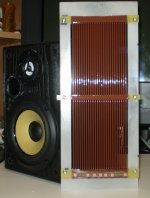
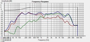
I have been building a simple ESL speaker lately. Finally got around to measure the frequency response. Using REW and UMIK-1.
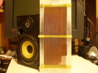
ESL is 37x12cm with 4mm steel rods from ikea as stators. 3.8um film and 1.5mm distance between stator and film.
I have four transformers with totally ~150:1 ratio. Running roughly 4.5kV bias.
The efficiency is not super high, as expected. I am using a 1000W amp, but when I start playing a bit louder the film sparks to the stators everywhere. The whole speaker lights up with Purple sparks. So it is not just one spot.
Stators are isolated with 3M 1350-1 tape. Roughly four layers. I tested them with 12kVDC and there was no problem then. Perhaps it is different when installed in a speaker?

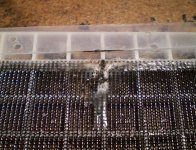
One of the stators Before insulation.

Two inches from speaker

8 inches

1m (3 feet) from speaker.
Any comments?
I have been building a simple ESL speaker lately. Finally got around to measure the frequency response. Using REW and UMIK-1.
ESL is 37x12cm with 4mm steel rods from ikea as stators. 3.8um film and 1.5mm distance between stator and film.
I have four transformers with totally ~150:1 ratio. Running roughly 4.5kV bias.
The efficiency is not super high, as expected. I am using a 1000W amp, but when I start playing a bit louder the film sparks to the stators everywhere. The whole speaker lights up with Purple sparks. So it is not just one spot.
Stators are isolated with 3M 1350-1 tape. Roughly four layers. I tested them with 12kVDC and there was no problem then. Perhaps it is different when installed in a speaker?
One of the stators Before insulation.
Two inches from speaker
8 inches
1m (3 feet) from speaker.
Any comments?
Last edited:
Ideas / Comments.
- Step up is very large, maybe reduce it for better high frequancy performance.
- Too small for full range, so make it a tweeter, and remeber overloading tweeters in testing is easy.
- Very large stator gap for a midrange / tweeter. I think you shodul be able to get away with 0.5 - 1 mm stator gap.
- Segment the driver for better off axis performance.
- Mount on a wider baffle for more midrange.
- Make a 500 / 800 Hz cross over, and add a bass driver before judging volume.
- Rebuild now you have ared the driver.
- Try some felt / wool behind it.
- Coat the rods with electical varnish.
Last edited:
Your curves look pretty much correct for a panel of that size.
I have been experimenting with similar sizes as well.
Did you use a SPL meter to calibrate your graphs with?
Owen hit on pretty much most points that should be taken into account.
Even though you have tested your coating material up to 12Kvdc it can have much different characteristics with AC signals.
Especially at the highest frequency's you will experience a higher stress in the coating's durability to resist punch through.
Once this happens you will never be able to properly seal it again and a new coating needs to be applied if your construction allows for it.
I can't tell if your rod's are 100% coated or just on one side.
If it is just on one side near the diaphragm and not on the other then this is not enough.
I2Kv will easily jump over to the bare side or a weaker spot in the coating by as far as a 1/2" or more.
I have many pictures of such tests in these threads, if you can't locate them I can post the links for you.
The stator coating needs to be contiguous without any breaks, gaps or cracks in it.
Lately I have been using a similar step up of 1:160 and as high as 1:250 or so in some tests and the voltage can get extremely high!!!
My main amplifier (Crown DC300A II) is capable of 58.5V peak and I have had as much as 25Kv across the stator's at full tilt before coating failure was the ultimate demise of my little panels.
My measured SPL at this point was well above +106db at 1 meter as measured.
Using a 6.8Kv bias and a 4V-5V peak signal into my 1:160 step-up I was getting in the 89db to 91db range for efficiency for my 3.25" x 9.75" with a 1.9mm (.075") d/s or so.
I did have to increase the d/s to about 2.5mm (approx .100") achieve satisfactory results below 300Hz range for that size panel due to the diaphragm clipping in to the stator's.
For this setup as measured I was getting +105db at 1 meter with just a 100watt amplifier at 40Vpeak into the transformer's.
Since I use them for nearfield listening I am much closer than one meter, and as you can imagine this is much much louder when close up.
For instance if you can measure 100DB at 1 meter it is +110db right at the panel 1cm away.
I verified this with my SPL meter at 1Khz.
Getting above this kind of voltage range (above 40Vpeak into 1:160 or even 1:250) has proven to be very difficult and I did a lot of testing of different coatings.
So far the best and cheapest coating that I have gotten good results out of is common Clear Acrylic Enamel Spray paint at 1900v to 2100v per mil for a point of punch through.
Stay away from any types that have a pigment except for the red primer as it is loaded with Talc as a filler.
Especially White, and blacks as well.
In a few tests I have found the dielectric strength may be just slightly better for the primer than just the clear type by itself at closer to 2200V per mil.
If you must have color then do just one coat on top of the primer and then use a heavy coat of clear after that.
My latest method is a coating of only 6 to 8 mil and can contain 14kv with no punch through.
You didn't mention your rod spacing having to little of an open area can also reduce your overall output as well.
Try to get no less than about 40% to 45% of open area. this will also help to provide some dampening as well.
Of all of my panels the ones that had the most open area seemed to sound the best in SQ.
4mm rods seem to be a bit large especially after you add your coating thickness.
I wanted to make some panels to see if this actually has much of an effect. One of the very First articles I read on DIY ESL's used such large rods and it too was very inefficient.
Thus it is the reason I used wire mesh for my First choice of Stator material.
Although my latest panel does use a 1/16" TIG rod design.
I do plan on using a .045 or .035 rod for the next one as by the time I got the stator's coated they are +2mm (.082") in diameter.
This helps to make a more concentrated and even static field per area of the stator's surface.
Once I was able to get my voltages up to par my original panels failed miserably compared to the set that was designed for such voltages and they were both the exact same size.
I could never get them past 3KV or so of bias or signal do the arcing and coating issues.
They only got loud enough to just hear them as they lacked very much in realm of performance.
I could run my good set with at 6.8KV with a D/S of only .070" or so and peak Stator Voltages up to 10-15Kv all day.
Of course this was the limit of that particular panel design but I was able to use it with a 10 TO 12Kv bias for a short time as well at +110db.
This also allowed me to prove that every time you double the bias you get 6db more efficiency.
That means an incredible 12db more going from 3Kv of bias to 12Kv of bias!!
Now these were some extreme voltages that were meant for testing only as there are practical limits due to the characteristics of the materials being used.
Yes, I too pushed them to the point of the air was ionizing in the gap but the coating resistance was high enough that it did not cause any punch through or burn holes in the diaphragm as observed in earlier attempts.
When this First ultimate level was reached I didn't have an SPL meter at the time but I assure you what I getting out of such a small panel was overwhelming!!!
I first started out with the very same panel hardly usable as a headphone driver!!
Then I was plagued with a burned coating and I was never able to repair back to that level.
Although, I was still able to continue with my tests and eventually did my calibrated measurements for reference.
I then finally made a new panel for such voltages, but, I haven't the time still, to mount a diaphragm and test it.
But it has surpassed all of the voltage tests so far.
FWIW
jer")
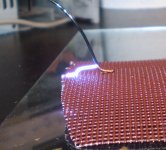
P.S. Sorry that I don't have these photos in proper order, But these show my old build my High performance build that used Powder Coating (black one), Its failure and the frequency response of it.
The arc tests are at 13.8Kv.
And my newest build.
I have been experimenting with similar sizes as well.
Did you use a SPL meter to calibrate your graphs with?
Owen hit on pretty much most points that should be taken into account.
Even though you have tested your coating material up to 12Kvdc it can have much different characteristics with AC signals.
Especially at the highest frequency's you will experience a higher stress in the coating's durability to resist punch through.
Once this happens you will never be able to properly seal it again and a new coating needs to be applied if your construction allows for it.
I can't tell if your rod's are 100% coated or just on one side.
If it is just on one side near the diaphragm and not on the other then this is not enough.
I2Kv will easily jump over to the bare side or a weaker spot in the coating by as far as a 1/2" or more.
I have many pictures of such tests in these threads, if you can't locate them I can post the links for you.
The stator coating needs to be contiguous without any breaks, gaps or cracks in it.
Lately I have been using a similar step up of 1:160 and as high as 1:250 or so in some tests and the voltage can get extremely high!!!
My main amplifier (Crown DC300A II) is capable of 58.5V peak and I have had as much as 25Kv across the stator's at full tilt before coating failure was the ultimate demise of my little panels.
My measured SPL at this point was well above +106db at 1 meter as measured.
Using a 6.8Kv bias and a 4V-5V peak signal into my 1:160 step-up I was getting in the 89db to 91db range for efficiency for my 3.25" x 9.75" with a 1.9mm (.075") d/s or so.
I did have to increase the d/s to about 2.5mm (approx .100") achieve satisfactory results below 300Hz range for that size panel due to the diaphragm clipping in to the stator's.
For this setup as measured I was getting +105db at 1 meter with just a 100watt amplifier at 40Vpeak into the transformer's.
Since I use them for nearfield listening I am much closer than one meter, and as you can imagine this is much much louder when close up.
For instance if you can measure 100DB at 1 meter it is +110db right at the panel 1cm away.
I verified this with my SPL meter at 1Khz.
Getting above this kind of voltage range (above 40Vpeak into 1:160 or even 1:250) has proven to be very difficult and I did a lot of testing of different coatings.
So far the best and cheapest coating that I have gotten good results out of is common Clear Acrylic Enamel Spray paint at 1900v to 2100v per mil for a point of punch through.
Stay away from any types that have a pigment except for the red primer as it is loaded with Talc as a filler.
Especially White, and blacks as well.
In a few tests I have found the dielectric strength may be just slightly better for the primer than just the clear type by itself at closer to 2200V per mil.
If you must have color then do just one coat on top of the primer and then use a heavy coat of clear after that.
My latest method is a coating of only 6 to 8 mil and can contain 14kv with no punch through.
You didn't mention your rod spacing having to little of an open area can also reduce your overall output as well.
Try to get no less than about 40% to 45% of open area. this will also help to provide some dampening as well.
Of all of my panels the ones that had the most open area seemed to sound the best in SQ.
4mm rods seem to be a bit large especially after you add your coating thickness.
I wanted to make some panels to see if this actually has much of an effect. One of the very First articles I read on DIY ESL's used such large rods and it too was very inefficient.
Thus it is the reason I used wire mesh for my First choice of Stator material.
Although my latest panel does use a 1/16" TIG rod design.
I do plan on using a .045 or .035 rod for the next one as by the time I got the stator's coated they are +2mm (.082") in diameter.
This helps to make a more concentrated and even static field per area of the stator's surface.
Once I was able to get my voltages up to par my original panels failed miserably compared to the set that was designed for such voltages and they were both the exact same size.
I could never get them past 3KV or so of bias or signal do the arcing and coating issues.
They only got loud enough to just hear them as they lacked very much in realm of performance.
I could run my good set with at 6.8KV with a D/S of only .070" or so and peak Stator Voltages up to 10-15Kv all day.
Of course this was the limit of that particular panel design but I was able to use it with a 10 TO 12Kv bias for a short time as well at +110db.
This also allowed me to prove that every time you double the bias you get 6db more efficiency.
That means an incredible 12db more going from 3Kv of bias to 12Kv of bias!!
Now these were some extreme voltages that were meant for testing only as there are practical limits due to the characteristics of the materials being used.
Yes, I too pushed them to the point of the air was ionizing in the gap but the coating resistance was high enough that it did not cause any punch through or burn holes in the diaphragm as observed in earlier attempts.
When this First ultimate level was reached I didn't have an SPL meter at the time but I assure you what I getting out of such a small panel was overwhelming!!!
I first started out with the very same panel hardly usable as a headphone driver!!
Then I was plagued with a burned coating and I was never able to repair back to that level.
Although, I was still able to continue with my tests and eventually did my calibrated measurements for reference.
I then finally made a new panel for such voltages, but, I haven't the time still, to mount a diaphragm and test it.
But it has surpassed all of the voltage tests so far.
FWIW
jer
P.S. Sorry that I don't have these photos in proper order, But these show my old build my High performance build that used Powder Coating (black one), Its failure and the frequency response of it.
The arc tests are at 13.8Kv.
And my newest build.
Attachments
-
 Screen Stator2.jpg69.1 KB · Views: 446
 -
 ESL4.jpg142.9 KB · Views: 121
 -
 Arcing Around the Coating But Not Through It.jpg103.6 KB · Views: 124
 -
 ESL.jpg215.2 KB · Views: 124
 -
 Ready for The Diaphragm.jpg168.3 KB · Views: 137
 -
 sharp edges.jpg728 KB · Views: 131
 -
 14Kv closeup.jpg143.2 KB · Views: 149
 -
 todays test b mic.jpg252.7 KB · Views: 128
 -
 Resurected.jpg76 KB · Views: 120
 -
 ESL1.jpg99.2 KB · Views: 143
Last edited:
Thanks for the comments!
I did use a woofer when listening to the speaker. But I only have one speaker, I know that can be a bit misleading.
I have actually segmented the stators. I tried it and it makes a big difference. With all segments running it starts to measure badly only 5 degrees off axis. With only the middle rods running I got 10-15 degrees with good response.
I have no intention of using these fullrange, even if they sound quite nice down to 100Hz. My goal is 300Hz or so.
I only used the calibration file I got with the microphone, dont know how accurate it is. I did measure a 6" Seas woofer I had lying around and the efficiency(frequency response) is similar to its datasheet.
My rods arent coated at all. I just wrapped them in four layers 1350-1 transformer tape. This is supposed to handle 5500V per layer. And yes, the rods are completely covered. And the open ends with Connections are immersed in epoxy. That seems to work fine. The sparks are not concentrated to spots, but all over the stator. Looks fantastic in the dark
I run 100V peak on my transformers. Should give 15kVpeak over the stators. Is that too much?
With pink noise I get something like 93dB(C). I didnt measure 1kHz or any other tone, that is my next taks. It gets really loud with 1kHz, but not so with Music.
Having the HP filter at 250-500Hz i dont really see the film moving much at all. Perhaps that will come when I get better efficiency.
I feel like I dont have as good efficiency as I was hoping for. Perhaps the rods are the problem. The open area is 50% (4.5mm stator incl tape) and mounted with 9mm C-C. I am following you thoughts here. The part of a 4mm rod that is Close to the film is very small. The field may not be as strong/uniform as with a mesh or smaller rods.
Is the ionizing of air dependent on the insulation? I had a lot of it. Smelled like a welding shop... But I have no problem with any permanent destruction. All that happens is that the film has to recharge and then the sound comes back.
My hope is that I can make a panel that plays a bit loudly 300-20kHz. They sound really nice, the typical ESL sound is definitely present. It is the lack of SPL I am concerned with. I will measure with tones and see what I actually get out of it.

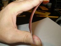
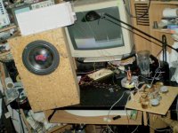
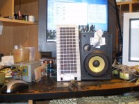
The stator insulated, being glued with epoxy.

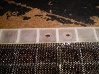
Film attached and coated, with sticky tape just waiting for the other stator.

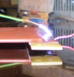
Playing. The business cards are there to define the distance between stators.
I did use a woofer when listening to the speaker. But I only have one speaker, I know that can be a bit misleading.
I have actually segmented the stators. I tried it and it makes a big difference. With all segments running it starts to measure badly only 5 degrees off axis. With only the middle rods running I got 10-15 degrees with good response.
I have no intention of using these fullrange, even if they sound quite nice down to 100Hz. My goal is 300Hz or so.
I only used the calibration file I got with the microphone, dont know how accurate it is. I did measure a 6" Seas woofer I had lying around and the efficiency(frequency response) is similar to its datasheet.
My rods arent coated at all. I just wrapped them in four layers 1350-1 transformer tape. This is supposed to handle 5500V per layer. And yes, the rods are completely covered. And the open ends with Connections are immersed in epoxy. That seems to work fine. The sparks are not concentrated to spots, but all over the stator. Looks fantastic in the dark
I run 100V peak on my transformers. Should give 15kVpeak over the stators. Is that too much?
With pink noise I get something like 93dB(C). I didnt measure 1kHz or any other tone, that is my next taks. It gets really loud with 1kHz, but not so with Music.
Having the HP filter at 250-500Hz i dont really see the film moving much at all. Perhaps that will come when I get better efficiency.
I feel like I dont have as good efficiency as I was hoping for. Perhaps the rods are the problem. The open area is 50% (4.5mm stator incl tape) and mounted with 9mm C-C. I am following you thoughts here. The part of a 4mm rod that is Close to the film is very small. The field may not be as strong/uniform as with a mesh or smaller rods.
Is the ionizing of air dependent on the insulation? I had a lot of it. Smelled like a welding shop... But I have no problem with any permanent destruction. All that happens is that the film has to recharge and then the sound comes back.
My hope is that I can make a panel that plays a bit loudly 300-20kHz. They sound really nice, the typical ESL sound is definitely present. It is the lack of SPL I am concerned with. I will measure with tones and see what I actually get out of it.
The stator insulated, being glued with epoxy.
Film attached and coated, with sticky tape just waiting for the other stator.
Playing. The business cards are there to define the distance between stators.
Very good !!!
It seems to be working as it should.
My peak SPL measurement's were done using tones, Yes they were the loudest compared to any noise or music signals.
What you have is the air ionizing in the gap and not necessarily any arcing.
I have been to this level before.
Even though raising the bias voltage will give you more efficiency your peak SPL is still limited by the breakdown of the air as this reduces the force that can be applied to the diaphragm.
I am not sure if pushing the voltages any higher can yield more SPL at this point.
Due to stator coating issues on my last set I was never able to test at that level again,thus the reason I had to build a new design.
Due to having less surface area and displacement it takes higher than normal voltages compared to a larger panel to really perform!!
I was still quite impressed when I had finally got my small to such level of performance.
They make really super midrange /tweeters and I used to listen to them full range at lower levels with out a woofer as well.
In my last battery of tests I never did listen to them in stereo as I was quite content with what I was hearing out of just one panel!!!
I am very glad to hear of your report about the dispersion issue and I am very happy to know that it too works well.
Cheers!!!
jer
Last edited:
So you Think my only option for higher SPL is higher D/S or larger panel?
I Think I would still benefit from a more uniform field. If I use a stator with more Surface area Close to the film I should be able to have more SPL for the same voltage. But the film will move more, so I may need to increase D/S. Thoughts?
I Think I would still benefit from a more uniform field. If I use a stator with more Surface area Close to the film I should be able to have more SPL for the same voltage. But the film will move more, so I may need to increase D/S. Thoughts?
Yes, more surface area always prevails.
If you increase your D/S you can increase the bias to compensate for the loss in efficiency.
If you are trying to get low frequency performance than you can add some side wings and this will help a little bit.
Your lowest frequency performance will set the bar for your overall peak SPL when the panel is EQ'ed to be flat at a distance.
This is where you must choose your crossover frequency wisely.
This is discussed in this thread,
http://www.diyaudio.com/forums/planars-exotics/48120-experiences-esl-directivity-2.html#post2203058
There are some spread sheets help you with the calculations as well.
The the benefit of using a segmented stator design is the ability of being able to go wider as well.
This calculator is quite accurate as well,
Electrostatic Loudspeaker (ESL) Simulator
It is possible you could benefit from a from a different stator material, But I don't know how much of a factor this would be.
I have read reports of DIY'ers using a certain hole size (.120" to .170") when using perforated metal, and as they were used to the characteristics of their system they decided to build another one only using a larger sized hole diameter such as 5/16" dia.
Most have reported that even though it sounds the same or better due to a larger open area, they did take a hit on efficiency as well.
It was not stated on how much was lost.
I wanted to experiment with this using some wire mesh as mine are common window screen of 16 x 16 or so per square inch.
By the time I got around to doing this I couldn't find any 1/8" mesh anymore, however I do have same 1/4" mesh that I have been wanting to make a same sized (3.25"x 9.75") sample panel to try out.
There have been quite a few discussions on this but I forget which threads they are in.
jer
Last edited:
Most have reported that even though it sounds the same or better due to a larger open area, they did take a hit on efficiency as well.
It was not stated on how much was lost.
From the Walker equation we know that SPL is proportional to stator current.
We also know that stator current is proportional to stator-to-stator capacitance.
So, you can get a pretty good estimate of the efficiency hit by measuring stator-to-stator capacitance and comparing it to the capacitance calculated for flat plate air capacitor of the same area.
In general, if the stator openings are similar in size(or smaller) to the D/S spacing there is little efficiency loss.
More details here:
http://www.diyaudio.com/forums/planars-exotics/246846-first-time-esl-builder-12.html#post3881204
Thanks!
I used the quadesl.nl simulator. I am roughly 8dB off around 500Hz with my voltages.

This is the results of the 54Vrms test. I measured the ratio of the transformers at lower voltages and found it to be ~125. So 54Vrms should be 6k7Vrms on the stators.
95-96dB at 500Hz is not that impressive.

Going from 3Vrms to 54Vrms increases the SPL quite a lot. I Think in theory it should be 25dB, measured difference is ~22dB.
I Think I will measure capacitance between the stators. Thanks for the link Bolserst.
I want to see what it going on with this panel Before I start building a bigger one.
I used the quadesl.nl simulator. I am roughly 8dB off around 500Hz with my voltages.
This is the results of the 54Vrms test. I measured the ratio of the transformers at lower voltages and found it to be ~125. So 54Vrms should be 6k7Vrms on the stators.
95-96dB at 500Hz is not that impressive.
Going from 3Vrms to 54Vrms increases the SPL quite a lot. I Think in theory it should be 25dB, measured difference is ~22dB.
I Think I will measure capacitance between the stators. Thanks for the link Bolserst.
I want to see what it going on with this panel Before I start building a bigger one.
There is the possibility that your bias voltage may not be where you expect it to be.
By using your info and substituting for a 2.5kv bias the simulator shows approximately your current results.
This can be caused form some sort of leakage path or something.
To high of a Diaphragm resistance and connections can play a big part of this as well, not allowing it to completely fully charge.
Not knowing the full details of your construction HV can leak through any Wood components as well.
When I First started building HV resistor dividers I found out quickly that my bias voltage was not anywhere near what I had expected it to be and the result was poor efficiency.
That was when I designed and built my variable HV supply for such tests.
What I had calculated my supply to be putting out at 5.5kv or so was actually around 3Kv and less when I hooked it up to the panel.
Not to mention loading errors of my measurement system at the time that caused it to drop a bit more because the current supply was not design to supply the extra current needed to maintain the voltage level.
There were many times after taking the panels apart and re-assembling them, that they didn't perform as well or even not at all.
This was mostly due to leakage paths caused form handling the parts or failed coating connections or even the coating for that matter.
On few instances my coating develop a continuous crack around the perimeter of the mounting frame causing it to not charge properly or even not at all.
I was using the original formula Licron at the time and it turned out that it was a bit brittle and could crack if it was not thick enough in that area.
There is a point were the coating can have to high of a resistance yielding a poor output as well, I have had this happen with "Crystal" but very often like twice I think this has happened to me.
You get better at applying it after a few tries.
You didn't mention what you are using for a coating?!!!
I have known others to go through all of this only to find that the coating failed or is failing.
Coating both sides of the diaphragm can cause such issues as well, only coat one side.
It could be a number of things but for that voltage range I was getting getting +105db at 1meter with test tones at a bias of about 6Kv to 7.5kv or so.
I will try to get mine new panel running in the next few days or week as I am very curious and would like to show some solid results again rather then trying to remember my numbers from over two to four years ago.
My newest panel panel is designed for such high voltages without having any of the flashover issues I had encountered in my earlier tests.
Cheers!!
jer
Last edited:
I thought about the bias voltage too. I used an insulation tester that provides up to 12kVDC as a source for these last tests. Running 5kV I cant even see the current meter move, so I Think the supply is really 5kV. I have 40Megaohm in series with the film. But I tried 20Megaohm and it measured similar.
But yes, I thought my EHT supply would produce 7kV. I Think I get 4.5-5kV.
I am using Shackman coating. I dont really know what it is, but it worked well when recoating a pair of Audiostatics. I followed the instructions, but I may have made a mistake somewhere on the way. I only coated one side.
At what frequency are you getting 105dB and at what drive voltage and distance?
I am starting to Think that I should build a small 8x10cm panel to test these things on. My panel isnt big, but it would just be faster to test different stators in a smaller frame.
What distance were you measuring at? This measurement looks different than the ones you showed in post#1.I used the quadesl.nl simulator. I am roughly 8dB off around 500Hz with my voltages.
There is a known problem with some of the UMIK-1 calibration files, giving SPL that is off by 6dB when used with REW.
Have you measured a dynamic tweeter/speaker with known sensitivity to ensure that your measurement setup is properly calibrated?
I have found near field measurement to be the easiest way to compare SPL with theory.
In case you hadn't seen them, there were two short threads on this topic.
http://www.diyaudio.com/forums/plan...w-sensitivity-full-range-esl.html#post3006565
http://www.diyaudio.com/forums/planars-exotics/199943-measuring-sensitivity-esls.html#post2771817
I agree with your approach.I Think I will measure capacitance between the stators. Thanks for the link Bolserst.I want to see what it going on with this panel Before I start building a bigger one.
Work out any problems(materials, adhesives, coatings, bias voltage, etc) with small test panels before wasting time and money on you final larger panels.
I always do my calibrated measurements at 1 meter and typically at 1Khz.
I also use 20-20Khz sweep tests too.
My drive voltge for 105db was about 40Vpeak at a bias of 6.8kv and a 1:160 ratio.
This setup gives me aprox. 89db at 1 meter for a 4-5 volt peak input signal with a D/S of .075".
I had posted my calibrated measurements for 95db here,
http://www.diyaudio.com/forums/plan...system-design-review-request.html#post4125373
jer
Last edited:
So I had some time to measure the ESL again this weekend.
I calculated the capacitance 38*12cm and 0.3cm stator to stator. I Think I calculated 134pF. I measured 114pF with a stable measurement (instrument used in development of inductive Components). I Think that seems very good.
I also measured at 4cm from the film. With 5kV bias and 8kV bias from the high voltage tester.

5kV bias

8kV bias
This seems way too low compared to the simulation.
Thoughts?
I calculated the capacitance 38*12cm and 0.3cm stator to stator. I Think I calculated 134pF. I measured 114pF with a stable measurement (instrument used in development of inductive Components). I Think that seems very good.
I also measured at 4cm from the film. With 5kV bias and 8kV bias from the high voltage tester.
5kV bias
8kV bias
This seems way too low compared to the simulation.
Thoughts?
I agree, if I understand your setup this is -8dB to -10dB below expected output.This seems way too low compared to the simulation. Thoughts?
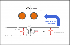
Before I make some suggestion, I need to make sure I understand your setup during the measurement, and the dimensions of the stator rods, stator insulation tape, and air-gap. Based on your posts, I believe the attachment defines your setup. Is this correct?
Attachments
Almost!
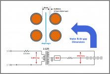
The stators are correct. I use 3ohm resistor, and 3Vrms gives me 375Vrms on the secondary side.
Arg! Got mixed up with the Esl Segmentation thread…correction attached.
http://www.diyaudio.com/forums/planars-exotics/265094-esl-segmentation.html#post4126514
One other question I forgot to ask is if you were using any segmentation during the measurements, or were all the stator rods uniformly driven. The reason I ask is that you mentioned segmentation back in post#2 but didn’t given any details on resistances used or how many stator rods were in each segment. This will affect the sensitivity measurements.
If all stator rods were uniformly driven with 375Vrms, your measurements at 4cm are 12dB – 15dB less than expected. This is a significant short fall. The 85% measured capacitance vs flat plate theory would account for -1.5dB of it, that still leaves a lot to account for. Since you have measured the applied stator voltage, the only other possible reason for the low sensitivity is you are not getting the charge on the diaphragm you think you are with 5kV bias applied. This could be the result of several things:
1) Diaphragm coating not conducting well. You can test this by breathing or exhaling warm moist air onto the coating side of the diaphragm. If the sensitivity suddenly improves, it is likely that the coating is not conducting properly.
2) Significant leakage path. You mentioned in post #12 you weren’t measuring any leakage, so this is not likely the problem.
3) The bulk resistivity of the mylar insulation is too high compared to the resistivity of air. The result is that a large portion of the DC bias voltage is lost across the insulation leaving a smaller portion across the airgap to charge the diaphragm.
http://www.diyaudio.com/forums/plan...truct-cube-louver-acoustat-7.html#post2154621
Jim Strickland experienced this when he was experimenting with different types of insulation for the Acoustat stator wires like PE/Teflon. The fix was to switch back to the Janszen patent recommendation of PVC.
“…Strickland told me once that he'd seen lab speakers that actually played louder after power down of the bias supply than before (for a while anyway), and sometimes he observed audio phase reversals at that time too. This was all with PE before he switched to nice leaky PVC. Weird science…”
http://www.diyaudio.com/forums/planars-exotics/58407-insulated-vs-bare-metal-stators.html#post658044
http://www.diyaudio.com/forums/planars-exotics/58048-fresh-esl-research-2.html#post653417
If you have enough rods to make an uninsulated version of your stators, this would be the best test to see if the uninsulated stators match SPL predictions. This is not as scary is it sounds. You will find that uncoated wires and round rods do not have the arcing problem that uncoated perforated sheet metal does. Basically, the rods will arc at nearly the same voltage as your current insulated stators with the same size airgap. The difference will be that instead of purple corona and the smell of ozone, you will get high current arcing that often sets the diaphragm on fire. So, keep the volume down when testing uninsulated stator rods until you know the limits.
In place of testing an uninsulated version of your stator, you can try the following.
a) Turn off or disconnect the HV supply and connect the diaphragm directly to the transformer CT(center tap). Leave it that way over night.
b) With the diaphragm still connected to the CT, apply audio to the stators and confirm you get essentially zero output.
c) Remove connection from diaphragm to CT and hook up your HV supply between the diaphragm and CT. Play audio at high levels for a few minutes.
d) Turn off and remove HV supply and reconnect the diaphragm to the CT. Note there may be a small spark as you are discharging the diaphragm.
e) With diaphragm still connected to the CT, play audio. If you hear significant output, you have confirmed that charge is being stored in the mylar insulation. If you look at the impulse response, you will find it is inverted compared to when you had the HV supply hooked up.
If this is found to be the case, you might try using PVC heatshrink tubing to cover your rods instead of the mylar tape.
Attachments
I appreciate all the information given in this thread, thanks!
I measured the impulse and the SPL at 1kHz with and without EHT according bolsterst last test method. Had the panel disconnected for a week. Put the mic 8cm from film. I started without EHT, and connected the film to the center tap. When I played pink noise I could turn up the amp, but I still didnt get SPL over 55dB (which is noise floor in the room).
With EHT I can get 100dB of pink noise. With film connected directly to the center tap I got 75dB. I dont know how significant that is?
I have to turn off the EHT before removing it and then I can see the SPL go down.
When I connect the film to center tap the impluse response switches polarity.

Film connected to EHT

Film connected to CT, no EHT.
Am I thinking correct here?
When I remove the EHT and connect the film to the enter tap there should be no charge of the film at all. It should be similar to when I first started it up after being disconnected for a week. So the 75dB that I get when the EHT is removed must be from the charge in the tape on my stators.
I measured the impulse and the SPL at 1kHz with and without EHT according bolsterst last test method. Had the panel disconnected for a week. Put the mic 8cm from film. I started without EHT, and connected the film to the center tap. When I played pink noise I could turn up the amp, but I still didnt get SPL over 55dB (which is noise floor in the room).
With EHT I can get 100dB of pink noise. With film connected directly to the center tap I got 75dB. I dont know how significant that is?
I have to turn off the EHT before removing it and then I can see the SPL go down.
When I connect the film to center tap the impluse response switches polarity.
Film connected to EHT
Film connected to CT, no EHT.
Am I thinking correct here?
When I remove the EHT and connect the film to the enter tap there should be no charge of the film at all. It should be similar to when I first started it up after being disconnected for a week. So the 75dB that I get when the EHT is removed must be from the charge in the tape on my stators.
When I remove the EHT and connect the film to the enter tap there should be no charge of the film at all. It should be similar to when I first started it up after being disconnected for a week. So the 75dB that I get when the EHT is removed must be from the charge in the tape on my stators.
If the charge is on the stator tape how does it make sound?
- Status
- This old topic is closed. If you want to reopen this topic, contact a moderator using the "Report Post" button.
- Home
- Loudspeakers
- Planars & Exotics
- Measured my ESL attempt