two ways + multiple subs seems to be a good formula
there is a big quality cost of trying to go too low with just the two ways alone
the subs don't have to be close to the mains, in fact should be distributed to excite room modes differently then individually eq'd to get best bass in listening region
you really shouldn't want something moving as far as needed for 20 Hz sub bass to be trying to give coherent 1 KHz at the same time
I think the main compromise is how loud you want it to go, and the size of the listening room. My biamp'd 2 way sounds VERY good at as high a level as I'd ever want in my computer room (which is a bedroom in an apartment). I think being able to cross it at 500HZ with a 4 pole active crossover is what makes it so successful.
Very informative posts by all. From what I gather is if one makes it ported and compromises somewhat on SPL at reference level (if I understand it right it will be lower) would be a good trade-off I guess. Mind you that is If one strictly wants a two driver speaker system.
Regards
Regards
"there is a big quality cost of trying to go too low with just the two ways alone"
There will also be a huge problem with frequency modulation distortion (gargle) in any two-way with good bass.
I find it difficult to listen to 15" studio monitors for this reason, the 'gargle' on the vocals when bass is present is very annoying.
A 6-1/2", 8", or 10" two-way crossed around 80hz~ 150hz is a much better proposition.
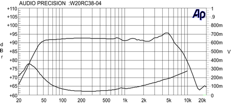
There are some nice 8's that have no bass, but are 93dB/2.83V/1M.
Shanghai Silver Flute Sound Co Ltd - China Exporter, Manufacturer | HKTDC
There will also be a huge problem with frequency modulation distortion (gargle) in any two-way with good bass.
I find it difficult to listen to 15" studio monitors for this reason, the 'gargle' on the vocals when bass is present is very annoying.
A 6-1/2", 8", or 10" two-way crossed around 80hz~ 150hz is a much better proposition.
There are some nice 8's that have no bass, but are 93dB/2.83V/1M.
Shanghai Silver Flute Sound Co Ltd - China Exporter, Manufacturer | HKTDC
Amen to that. +1"there is a big quality cost of trying to go too low with just the two ways alone"
There will also be a huge problem with frequency modulation distortion (gargle) in any two-way with good bass.
I find it difficult to listen to 15" studio monitors for this reason, the 'gargle' on the vocals when bass is present is very annoying.
A 6-1/2", 8", or 10" two-way crossed around 80hz~ 150hz is a much better proposition.
There are some nice 8's that have no bass, but are 93dB/2.83V/1M.
An externally hosted image should be here but it was not working when we last tested it.
Shanghai Silver Flute Sound Co Ltd - China Exporter, Manufacturer | HKTDC
"there is a big quality cost of trying to go too low with just the two ways alone"
There will also be a huge problem with frequency modulation distortion (gargle) in any two-way with good bass.
I find it difficult to listen to 15" studio monitors for this reason, the 'gargle' on the vocals when bass is present is very annoying.
A 6-1/2", 8", or 10" two-way crossed around 80hz~ 150hz is a much better proposition.
There are some nice 8's that have no bass, but are 93dB/2.83V/1M.
An externally hosted image should be here but it was not working when we last tested it.
Shanghai Silver Flute Sound Co Ltd - China Exporter, Manufacturer | HKTDC
Case closed. The end. That's why I asked why all this fascination with a 2 way.
Hitten
Your original question asked about the lower end.
I've made this comment in a few other threads, and was completely ignored. I expect to be ignored here again.
For a fuller, more impactful low end, use a cored inductor. Your measurements won't change. I know you don't want subjective input, sorry.
Changing from an air core inductor to a cored occasionally has a detrimental effect higher up.
It never hurts to try it.
There will also be a huge problem with frequency modulation distortion (gargle) in any two-way with good bass.
I find it difficult to listen to 15" studio monitors for this reason, the 'gargle' on the vocals when bass is present is very annoying.
Realize the issue you are describing has little to do with the size of the driver. It is all related to the Le(x) and Le(i) distortions.
Le(x) is inductance vs excursion. The coil is essentially an inductor. Put it around the steel pole and it becomes an iron core inductor. Iron core has far higher inductance than an air core with the same amount of windings, so by nature most woofer voice coils have high inductance. On inward stroke, the entire coil is around the steel core so Le is at its highest point. As the coil moves outward, the windings begin to go past the tip of the pole and Le drops. You can see a good example of this in the Altec/GPA 414 measured Le vs X. This is at +/-5mm excursion. The middle curve you see will be with the coil at rest in the center. The upper curve is the increased Le on the inward stroke. The lower curve is the decreased Le of the outward stroke.
_5mm.png)
This is what happens with the typical "S" shaped inductance curve with standard motors. In this case, being a 12" drive, a typical Xover point would be considered to be about 1200hz as it narrows to less than 90 degrees about that point. The problem is at 1200hz there is a difference in the impedance curve from about 15ohm on the outward stroke to 28ohm on the inward stroke! This means the level of output at the outward stroke is around 3dB more than the level on the inward stroke at that frequency. This is where the distortion and modulation comes from. In the case of a passive xover, the component values can be made based on the rest value of the curve. However, as the coil moves outward or inward, that curve changes and those values are no longer valid. The effort put into getting coherent phase through the xover region is now lost as the values aren't correct once the coil starts moving. In the case of an active Xover it is less of an issue, but a 3dB variation in the upper end of the woofer response just before the xover is not a good thing either.
In addition to this, realize that the actual impedance of the driver is changing. This means more power is being applied on the outward stroke than on the inward stroke. When we look at Le(i) which is flux modulation, this becomes even more of an issue. In any case when the coil is energized, it becomes and electromagnet. While it may seem small, it is very powerful. As it moves through the gap, it modulates, or pushes around the magnetic field generated in the steel top plate and steel pole by the permanent magnet. The more saturated the pole and top plate are, the harder it is for the field to move. However, even if fully saturated, the field will be pushed as more current is put into the coil. It is this permanent magnetic field that the energized voice coil pushes against to make it's movement. The problem is that the permanent magnetic field is now moving, so the coil is pushing off of something that is not stationary. This is a huge problem in terms of distortion. It is the only factor that causes both HD and IMD in the current domain.
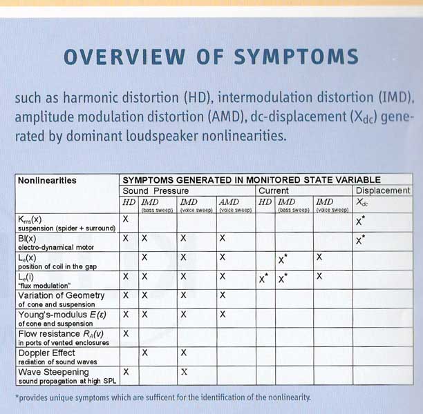
This is the most significant factor in terms of distortion within the motor itself yet it is rarely addressed properly. Part of that reason is its significance doesn't show up on the typical testing. If you look at a sweep taken to measure H2, H3, H4, H5, etc distortions the effects really don't show up at all. The reason is that if you cut a sweep into tiny segments, it is only measuring one frequency at time. If the sweep starts at 100hz and goes to 20,000hz, it is never playing more than on frequency at a time. Unfortunately music doesn't work that way. There are vocals over a kick drum hit or electric guitar at the same time as bass guitar. The way to simulate this is to play a tone at the Fs of the driver to generate high excursion on the driver. Playing at Fs assures minimal current as impedance is at the highest point. THEN run the sweeps. Upper end distortion will be seen magnitudes higher in this case if nothing is done to linearize inductance and reduce flux modulation.
That all said, the reason Luke can use the TD18H+ up to 500hz and still play down to 20hz at high excursion is because the woofer has been designed to do this. The Full Copper Faraday Sleeve on the pole addresses the flux modulation issue, and the change in Le with respect to excursion. While I don't have a curve from the TD18H+, this is one seen from the TD15X. All of the motors are very similar in concept. In this case, these measurements were not taken at only +/-5mm, but +/- 13mm. You can see that the impedance curves from rest, inward, and outward strokes overlay completely within any intended bandwidth. It isn't until over 5KHz that you can see the curves even begin to separate. Even at 20KHz there is very little difference. Keep in mind this is at +/- 13mm on a 15" driver.
_13mm.png)
In addition, the Full Copper Faraday Sleeve also eliminates the flux modulation. As the coil moves, large eddy currents are created that are shorted in the copper sleeve, preventing the permanent magnetic field from moving. The higher excursion at 20hz no longer modulates the response in the xover at 500hz in this design. The TD18H+ itself is quite flat to almost 2KHz. Once inductance and flux modulation are addressed, the only real limitation is based on the diameter of the driver which limits response to about 500hz if the intent is to keep a 90 degree wide pattern. We discuss the efforts used in the TD18H+ to achieve that in the following article.
http://aespeakers.com/designing-for-low-distortion-lambda-001-motor/
Case closed. The end. That's why I asked why all this fascination with a 2 way.
Well, it's not the end quite yet...
Here is a recipe, among few others:
1) a pair of TIW250XS
2) a pair of Radian PB950 with 3mil spacers provided by Radian
3) a pair of short horns
4) a pair of PWR-ICE250
5) a pair of very simple sealed enclosures
6) try few xover points that suits your tastes; most probably between 450hz and 1khz
7) apply EQ corrections where it's needed.
Total output will be limited by the TIW250XS but you'll get very decent SPL and dynamics... and probably 2-way speakers that beats in quality many of the commercial 3-way speakers out there.
"Realize the issue you are describing has little to do with the size of the driver."
You would be right, other than the FMD can be measured on a spectrum analyzer.
Even superlative constructed drivers (shorting rings, etc) show this problem in actual use.
FMD becomes quite objectionable with the bandwidth exceeds three octaves and the cone excursion exceeds 5mm.
You would be right, other than the FMD can be measured on a spectrum analyzer.
Even superlative constructed drivers (shorting rings, etc) show this problem in actual use.
FMD becomes quite objectionable with the bandwidth exceeds three octaves and the cone excursion exceeds 5mm.
"Realize the issue you are describing has little to do with the size of the driver."
You would be right, other than the FMD can be measured on a spectrum analyzer.
Even superlative constructed drivers (shorting rings, etc) show this problem in actual use.
FMD becomes quite objectionable with the bandwidth exceeds three octaves and the cone excursion exceeds 5mm.
I am not discounting the ability to measure, nor the significance of this FMD. There are only 2 causes though. One is change in acoustic loading on the diaphragm which is not very significant in most applications. The other is the clear difference in inductance from the inward and outward stroke as I explained. This causes higher level on the outward stroke and lower level on the inward stroke in most all drivers if the Le(x) has not been addressed.
The diameter of the diaphragm has no effect on this. The excursion also has no effect as the so called "doppler distortion" does not exist within the short distance changes we are seeing. If Le is linearized, keeping the magnitude of the upper end response equal throughout the stroke, this issue is eliminated.
The 5mm excursion and 3 octaves you mention would be a realistic excursion and bandwidth to experience this in a driver with typically varying Le. You can simulate easily. Play a 20hz tone to high excursion and play a 1KHz tone over it. Not only can you measure it, you can hear it. Address the Le(x) so that the response curve magnitude doesn't modulate, and this effect is nearly eliminated. The TD18H+ in this case can play 20-25hz with good excursion and up to 500hz without audibility of this effect.
Regarding FM distortion:
If a driver moves +-5mm at 50 Hz (which means bloody loud in case of 15" woofers and causing lots of severe distortion in the ear itself) this will lead to a peak cone velocity of 1.6 m/s approximately. I don't know wheter this is significant at all regarding the modulation of a simultaneously played tone of, let's say 500 Hz. I don't think it is significant at all.
The main reason for having large woofers in studio monitors is to HAVE them running at low excursion levels and therefore reduce all kinds of distortion modes and make them play effortless.
Regards
Charles
Thanks Gentlemen. I have little understanding of electronics (am graphic designer) but FM distortion, doppler distortion are new to me. Will read about them.
There ought to be an ideal tradeoff between cone area, excursion, frequencies produced with respect to least distortion the driver produces. Is there ?
Other thing is of all important criteria of a speaker driver like linear response, cone breakup, various distortion etc. what should one give most importance to in descending order of lets say 10 significant aspects of a speaker driver ?
Regards.
Hiten,1)There ought to be an ideal tradeoff between cone area, excursion, frequencies produced with respect to least distortion the driver produces. Is there ?
2)Other thing is of all important criteria of a speaker driver like linear response, cone breakup, various distortion etc. what should one give most importance to in descending order of lets say 10 significant aspects of a speaker driver ?
Regards.
1) Define "ideal tradeoff"
") .
.2) List your "10 significant aspects of a speaker driver", you will be lucky to find 10 designers that would agree with even the first, and most designers will give different weighting to the different parameters.
Look at John_E_Janowitz's recent posts, describing a speaker designed to eliminate various distortion elements evident in (most) speakers (like the Great Plains example), yet designers may still prefer the sound of the distortion to the speaker that has measurably better metrics.
Art
read Geddes as a somewhat contrary example? - he dismisses low order smooth nonlinear distortion of speaker drivers and concentrates on frequency response directivity
and has some listening data to back up the relative inaudibility of low order nonlinear distortions
does lead to "super sizing" - using pro drivers, waveguides with compression drivers in home loudspeakers to keep them from gross higher order distortions as the suspension, motor mostly linear regions are exceeded
Member
Joined 2009
Paid Member
The trade offs have dictated that the best sounding wide range two way that can play at "reference level" ends up being a ported 15" and a high frequency compression driver.
I've never seen a clear statement like this before. I've seen proponents for different approaches argue the relative merits etc.
If a large ported woofer + tweeter horn is the best sounding why are there so many speakers about today which don't conform to this approach ?
I find that many of the people who respond to these threads are extremely opinionated, and trying to be perfectionists, and aren't always in touch with what's practical in the real world. That "reference level" is way too general a term to actually mean anything. Is the speaker for use in a bedroom? a living room? or as a P.A. system for a band? Do you want to play hard rock at real world levels? Not me.
A friend of mine sold out to that idea that a 15 inch woofer and big horn tweeter was the way to go. Now he's stuck with these huge cabinets in his living room that sound OK, but not great. They're very efficient, which would be important if they were a PA system for a rock band or if they were used outdoors, or if they were going to be driven by a 5 watt SE tube amp (which is what he's doing). The cabinets are so big that they may actually create more room acoustics problems. One might ask, if they can make speaker drivers be highly efficient (95 - 100+dB, 1watt/1 meter) then why would so many speaker driver manufacturers make drivers that are so inefficient (83dB - 90dB)? Obviously because the less efficient drivers have higher fidelity, or they wouldn't sell. For in home use, I've never thought of efficiency as being a high priority.
With a 4 pole crossover at 500HZ, I find that I can run my 2 way speakers (8 inch kevlar woofers and 3 inch TC9FD Vifa for mid and tweeter) very loud and not notice the doppler distortion, but like I said before, I'm in a typical sized apartment bedroom. These are my computer speakers. My main speakers in the living room are tri-amp'd with a 12 inch woofer on each side, actively EQ'd to be acoustically flat to 20HZ. It's all about how loud you want to run them, room size, bass extension; it's a very subjective thing. No speaker is perfect. Everybody has a different idea of what tradeoffs are best for their particular application. I can only tell anyone what worked great for me, in my situation. I'd rather have a 2 way that's bi-amp'd with a 4 pole xover and active EQ pumping up the low bass, than a 3 way that has a passive crossover and no low bass boost.
Last edited:
This thread has been informative to me. I understand what you all are saying about query being too vague. Being newbie I don't know every aspect of speaker design. This is just to know possibilities. To be simple and precise I read lots of specification of various commercial two way models online. I guess average range reaches around 60 hz (+/-3dB)(Neumann model reached 50hz but are nearfield) on lower side, so was just curious to know with modern advances of driver designs if more good specs of lower range can be achieved or not. It doesn't have to be 20hz or so, which I presume would be not possible but 50hz or 40hz may be possible.
Thanks and regards.
Thanks and regards.
- Status
- This old topic is closed. If you want to reopen this topic, contact a moderator using the "Report Post" button.
- Home
- Loudspeakers
- Multi-Way
- Maximum lower end of frequency range achievable from two way speakers.