Hi Calvin,
I understand that you don't like to use high turn ratio transformer and thick spacers. In case that I like to make a pair of ESLs that is capable of low frequencies at around 100 Hz, -3db. What kind of transformer's turn ratio, stator dimensions, bias voltage, spacer thickness, and amp power would you recommend? The more details the better, please.
Wachara C.
Hi,
the answer is not easy, because there are several factors to be thougt of.
Personally I´d increase membrane area considerably, especially in the wide direction, to still allow for small excursions and a stator-stator distance of no more than 4mm. I´d set the mechanical tension high, that the Fs would be around 80Hz.
Example: Panel of 150x60cm ->0.9m², Spacer 2mm-->s/s=4mm, C~2nF.
This translates to ~3k9Ohms@20kHz. Via the obligatory pair of 230/6V trannies with an U of ~69 the amp would see a minimum of ~0.8ohms (You will have to add a series resistor of 0.4-0.8Ohms anyway, so this U should work well).
The 2mm spacers would allow for ~3.5kV peak signal voltage (7kVp-p).
Divided by U this gives ~100Vp-p -->35Vrms --> 160W@8Ohm/320W@4Ohms the amp should be able to deliver.
You need to drive the panel via an crossover that dampens the Q of the Fs with a notch and thats HP´s Q itself is >1 to counter phase cancellation, its Fs beeing around 120Hz.
Such a wide and large panel has just one disadvantage..it needs a large room. For a realistic impression of stage the listening distance must be >4m. Less than that distance and it´s like listening to a giant Headphone")
jauu
Calvin
the answer is not easy, because there are several factors to be thougt of.
Personally I´d increase membrane area considerably, especially in the wide direction, to still allow for small excursions and a stator-stator distance of no more than 4mm. I´d set the mechanical tension high, that the Fs would be around 80Hz.
Example: Panel of 150x60cm ->0.9m², Spacer 2mm-->s/s=4mm, C~2nF.
This translates to ~3k9Ohms@20kHz. Via the obligatory pair of 230/6V trannies with an U of ~69 the amp would see a minimum of ~0.8ohms (You will have to add a series resistor of 0.4-0.8Ohms anyway, so this U should work well).
The 2mm spacers would allow for ~3.5kV peak signal voltage (7kVp-p).
Divided by U this gives ~100Vp-p -->35Vrms --> 160W@8Ohm/320W@4Ohms the amp should be able to deliver.
You need to drive the panel via an crossover that dampens the Q of the Fs with a notch and thats HP´s Q itself is >1 to counter phase cancellation, its Fs beeing around 120Hz.
Such a wide and large panel has just one disadvantage..it needs a large room. For a realistic impression of stage the listening distance must be >4m. Less than that distance and it´s like listening to a giant Headphone
jauu
Calvin
yes i did.it will be peice of cake.nooooo problemmmoooooo.right now.4 hours later i'm still very p.o.ed at my STUPID COMPUTER!say that 4 times real fast.why you say?i spent 4 1/2 hours today testing my transformer and writing a very detailed professional report for all of you and when i went to hit the save button it b.s.o.d.ed on me losing every last word, comma's AND periods i had spent 4 hours of typing i had done ,in 1 millisecond ,gone!and when i finaly calm down i will start over and redo it all over again hopefully without another b.s.o.d!but i can tell you this the test were very very interesting.and i'll try to have the report by tomorrow.meanwhile i'm still here.trying to get my mind off of smashing that stupid computer(don't worry i have several backups, just not of the report) while the power is still on! i'm okay,i can still talk about things just disapointed.you'll be superised at my findings.but more on that later. jer
Okay, everybody here are the new test results.my equipment is as follows,Hitachi v-425 oscilloscope,tenma model 72-455 signal generator.for the previous sweep test the following was used ,Phillips 16 bit pcs706 sound card set a at 96khz playback rate,mackie 32-8 mixer with a confirmed 0hz to 20hz response,and,is well within and exceeds factory specs and a aiwa cx-na707 digital audio system for an amplifier,all eq’s and signal processing are set to off.i hereby state that the data presented is to the best of my abilities and are as measured.i did not plan to take any pics at this time but if requested, I will be happy to repeat the test and post the results again with the pictures.the orignal pics posted of the sweep test were confirmed that it is the same of the amplifier, as suspected,by using a 10 ohm resistive load.i have chose to use the two 120v windings as any other winding posed an improper load for the signal generator which resulted in a distorted sine wave.also the two windings were matched,the rest were left open .test #1 generator on one 120v winding and the scope on the other 120v winding.test #2 the scope was connected to the new custom 10 turn winding all else is the same. Test #1 resuts are as follows,-2db 10hz ,-1db 20hz ,-.1db 60hz ,ruler flat 0db 100hz-50khz ,-1db 115khz ,-3db 200khz ,-6db 300khz ,-8db 400khz ,-6db 500khz ,-12db 600khz ,-7db 850khz ,-12db 1mhz .test #2 is as follows ,-2db 10hz ,-1db 20hz ,-.1 60hz ,flat 0db 100hz-50khz ,+1db 115khz ,bump of +7.5db 305khz ,dip of .7db 450khz ,bump of +9db 650khz ,+2.75 db 1mhz.test #1 shows possibly the effects interwinding capacitance above the audio range.it also refelcts the loading of the signal generator due to the self resonance’s of the transformer it self, as evedent in test #2.test #2 shows no degradation of frequency response due to interwinding capacitance only the highfrequency bumps due to the self resonances.this is confirmed by the leading edge ringing of a square wave.although I had discovered that my signal generator did not produce a very symeterical square wave below 100hz but was very acceptable anywhere above 100hz.after finding this only flaw with my generator I rechecked the input signal to the transformer and compared it to the output with the scope and I assure you that what went in did infact come out .the transformer produced both square and sine waves without any evidence of added distortion or saturation of the core,even at a higher power as previously tested(except for the square wave leadig edge ringing common in all transformers)throughout and exceeding the audio passband.these test results are the best of any transformer I have test to date power or audio,however it is the very first toriodal I have tested so far and being a 200 watt core I did exepct good results but not the impressive ones I got.i expect similar result from a smaller core due to the higher quality materials used than the e-I cores of yesteryear.when I aquire some different samples of sizes and/or brands I will test them and post their results also.i have proven that it is possible to use reverse engigneering by easily adding a new winding to determin the exsisting turns to create a custom ratio transformer to drive an esl panel instead of using two or more devices cutting down the risk signal degradation from using more than one device per panel or due to poor manufacturing tolerances and cutting cost for the average diy’er as we all know that transformers cost their weight in gold,it’s no joke! My next tests will be to study the effect of frequency response with a change of turns ratio by adding and deleting turns from the new custom primary. jer
Jer,
thanks so much for taking the time and helping me with my preamp, i posted that question before on here and no one had an answer, thanks, gotta jet to work, and will read your post asap! have a feeling it is very good, thanks again, cant wait to get some music in here.
just in case someone is reading, jerry took time out of his day, spoke with me and explained in simple terms how to fix my Adcom preamp, if there was a way to rewards points on this site, he would get 10 out of 10, very knowledgable person.
thanks buddy, made my day.
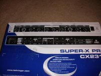
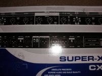
problem
here is the problem, iwish parts express would have told me that this does not have rca out. any suggestions before i send it back? i would imagine they make a plug for rca connection, but i think i would be better off with another cross over. but still open for suggestions, i do not want to modify the unit in any as it will void warranty. thank ya.
here is the problem, iwish parts express would have told me that this does not have rca out. any suggestions before i send it back? i would imagine they make a plug for rca connection, but i think i would be better off with another cross over. but still open for suggestions, i do not want to modify the unit in any as it will void warranty. thank ya.
Attachments

Sanders sound systems
Go here for some excellent information before starting to build you ESL
Sanders Sound Systems - Audio Related Articles
After reading this thread I am think of building a ESL of my own. I have the Martin Logan AERN i. They are 57" tall and look like Charlies ESLs.
I will build it just like his. Great work Charlie.
John
Ger, John,
Ger, parts express sent me the adapters today, un bias rca to that plug, j plug n plug, either way, problem solved. and why didnt you guve me a heads up that was for DJ equipment????It will work, thanks, many of them.
John, Charlie lended me Sanders book, that is where this thread started, i am still reading, this is the best site, and two of the most briallant people you will ever encounter, #1 >patience #2>some more patience #3> open up your wallet, and your mind, and again, some more patience, there for some reason is never enough.
Ger, going to fire up my pre amp as soon as i get home, thanks for the info. later. Mav
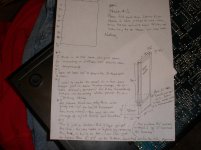
Here is avery rough idea i have, the idea is there, just not measurements. hope it makes sence. A hybrid is the back burner as i want a removable stat panel, the bottom is just to raise it off the the floor, provide good support, and for safety reasons, i have a dog, the last thing i need is him to hike his leg on this while it is on. so check it out and please dont garnish me too hard. disregaurd the second pic, wrong # on my end. just the sketch.
Attachments
Last edited:
Here is avery rough idea i have, the idea is there, just not measurements. hope it makes sence. A hybrid is the back burner as i want a removable stat panel, the bottom is just to raise it off the the floor, provide good support, and for safety reasons, i have a dog, the last thing i need is him to hike his leg on this while it is on. so check it out and please dont garnish me too hard. disregaurd the second pic, wrong # on my end. just the sketch.
Your sketch looks a lot like Sheldon Stokes' 2-piece hybrid ESL. Have a look at Sheldon's website: DIY ESL's Verison 1.0
You could use your 8" woofers in a separate box under the stats like Sheldon did. In any case, you shouldn't run your panels full range because the tandem toroids that you and I using aren't really good for that... you need some woofers or your bass will be poor.
Go here for some excellent information before starting to build you ESL
Sanders Sound Systems - Audio Related Articles
After reading this thread I am think of building a ESL of my own. I have the Martin Logan AERN i. They are 57" tall and look like Charlies ESLs.
I will build it just like his. Great work Charlie.
John
Thanks John,
I see you have a link to Sanders' Sound. I just drew up a speaker very much like Sanders' design-- have a DeltaCad drawing of it in fact, if you ever want an ESL like his.
Charlie,
i have my cross over, i will bring it with me tomorrow, cut off at 500hz 24db slope, and let my powered subs handle the low end. space is not a problem, I have not of heard of Sheldon's, but if it works, it was just a thought, just a way to upgrade later if i wish to. Now you are going to have me read another book, this is going to be interesting.
i have my cross over, i will bring it with me tomorrow, cut off at 500hz 24db slope, and let my powered subs handle the low end. space is not a problem, I have not of heard of Sheldon's, but if it works, it was just a thought, just a way to upgrade later if i wish to. Now you are going to have me read another book, this is going to be interesting.
yes, aka sds lab, this is the design i was trying to describe to you notice the dots they are support spacers to protecet against instability and high exerusions due to the large digphram width and length .this technieque was also used in the " high effiency electrostatic loudspeaker"article in the audio amatur magizine which used 6" wide panels and .032" or .040" spacers, i"ll have to find my copies to verify this.this design appeals to me and i will probaly implement it my next panles of 1' x4'.john thanks for the url i was not aware that roger wad posted the ampilfiers articles.those are the basis for the desgin i have been working on for the last few years, i have been protecting and savoring my twenty year old photo copies i have and always have a hard time trying to find them,thanks.
Anybody out there that have tested these transformers?
You can alter the step up between 1:9 and 1:129, from 150Hz.
Hammond Mfg. - Universal Tube Output - Push-Pull Transformers - (125 Series)
And buy them here (Europe):
Das Musikding - Hammond 125E output transformer hamm125e
You can alter the step up between 1:9 and 1:129, from 150Hz.
Hammond Mfg. - Universal Tube Output - Push-Pull Transformers - (125 Series)
And buy them here (Europe):
Das Musikding - Hammond 125E output transformer hamm125e
i have not tested that one,jonas,if i had one i would certainly test it for you and post the results. however i did find a few more trnasformers laying around today to mess with,1# a toriodial somewhwere between 100 to 150 watts i'm guessing because it is in a steel sheilding case and is about the same outside dimensions as the previous one i tested, the results were roughly the same almost identical except the resonate peak was at 840khz and less ringing on a square wave which resulted in a much cleaner waveform up to 120 khz.2# an e-i tube type power transformer which failed miseribly, it looked like a bandpass filter tuned to peak of 225hz not even at the 60 hz it was designed for and would not produce a square wave. 3# e-i tube type output for push pull el-34's(6ca7) showed good square wave from 10hz to 600hz with much much more ringing at 175khz ,sine wave test was flat 10hz to 2.2hz with a consistant slope from 2.2khz to +8db at 20khz continuoisly rising onto 100khz and up.which tells me why this amp sounded harsh and trebley,yet a warm low end, when i used it for my guitar (which i liked, but not for music)this is the same transformer i used to drive my mini esl driver when i discribed what i heard (i don't remember if it was this thread or another)coming from it.all of the test made no diffirence in response by swapping the primary for the secondary or vice versa except for the loading of the signal generator level which remained constant reguardless of frequency,changing only the voltage ratio.once again a toroidial power transformer wins hands down and unmodified. jer
- Status
- This old topic is closed. If you want to reopen this topic, contact a moderator using the "Report Post" button.
- Home
- Loudspeakers
- Planars & Exotics
- Material for ESL