just got home and read the link Charlie posted, i guess old things never die, that is the first pic i have seen that describes what intentions where the whole time. use the bottom for elecronics and be ready if i go TL, hmmm,
I start building Sunday, will post pics from start to finish, as well as video. No one, that i have seen on this site so far, has done start to finish w/pics, audio/video. if so, i would love to read about it, my first go at it, Mav.
I start building Sunday, will post pics from start to finish, as well as video. No one, that i have seen on this site so far, has done start to finish w/pics, audio/video. if so, i would love to read about it, my first go at it, Mav.
Guides before you start Building-P1
Extracts from the Martin Logan's operators manual of the AEON i
Signal Connection
Use the best speaker cables you can. The length and type of speaker cable used in your system will have an audible effect. Under no circumstance should a wire of gauge higher than #16 be used. In general, the longer the length used, the greater the necessity of a lower gauge, and the lower the gauge, the better the sound, with diminishing returns setting in around #8 to #12.
A variety of speaker cables are available whose manufacturers claim better performance than standard heavy gauge wire. We have verified this in many cases, and the improvements are often more noticeable than the differences between wires of different gauge. The effects of cables may be masked if the equipment is not of the highest quality. We also recommend, if possible, that short runs of speaker cable connect the power amplifier(s) and speakers and that high-quality long interconnect cables be used to connect the preamplifier and power amplifier. This results in the power amplifiers being close to the speakers, which may be practically or cosmetically difficult, but if the length of the speaker cables can be reduced to a few meters, sonic advantages may be obtained.
==================================
Electrostatic Advantages
==================================
How can sound be reproduced by something that you are able to see through? Electrostatic energy makes this possible.
Where the world of traditional loudspeaker technology deals with cones, domes, diaphragms and ribbons that are moved with magnetism, the world of electrostatic loudspeakers deals with charged electrons attracting and repelling each other.
To fully understand the electrostatic concept, some background information will be helpful. Remember when you learned in a science or physics class that like charges repel each other and opposite charges attract each other? Well, this principle is the foundation of the electrostatic concept.
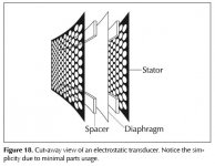
An electrostatic transducer consists of three pieces: the stators, the diaphragm and the spacers (see figure 18). The diaphragm is what actually moves to excite the air and create music. The stator’s job is to remain stationary, hence the word stator, and to provide a reference point for the moving diaphragm. The spacers provide the diaphragm with a fixed distance in which to move between the stators.
As your amplifier sends music signals to an electrostatic speaker, these signals are changed into two high-voltagesignals that are equal in strength but opposite in polarity. These high voltage signals are then applied to the stators.The resulting electrostatic field, created by the opposing high voltage on the stators, works simultaneously with and against the diaphragm, consequently moving it back and forth, producing music. This technique is known as push-pull operation and is a major contributor to the sonic purity of the electrostatic concept due to its exceptional linearity and low distortion.
Since the diaphragm of an electrostatic speaker is uniformly driven over its entire area, it can be extremely light and flexible. This allows it to be very responsive to transients, thus perfectly tracing the music signal. As a result, great delicacy, nuance and clarity are possible. When you look at the problems of traditional electromagnetic drivers, you can easily see why this is so beneficial. The cones and domes which are used in traditional electromagnetic drivers cannot be driven uniformly because of their design. Cones are driven only at the apex. Domes are driven at their perimeter. As a result, the rest of the cone or dome is just “along for the ride”. The very concept of these drivers requires that the cone or dome be perfectly rigid, damped and massless. Unfortunately, these conditions are not available in our world today.
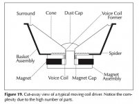
To make these cones and domes move, all electromagnetic drivers must use voice coils wound on formers, spider assemblies and surrounds to keep the cone or dome in position (see figure 19). These pieces, when combined with the high mass of the cone or dome materials used, make it an extremely complex unit with many weaknesses and potential for failure. These faults contribute to the high distortion products found in these drivers and is a tremendous disadvantage when you are trying to change motion as quickly and as accurately as a loudspeaker must (40,000 times per second!).
(See attachment)
Figure 18. Cut-away view of an electrostatic transducer. Notice the simplicity due to minimal parts usage.
Figure 19. Cut-away view of a typical moving coil driver. Notice the complexity due to the high number of parts.
Extracts from the Martin Logan's operators manual of the AEON i
Signal Connection
Use the best speaker cables you can. The length and type of speaker cable used in your system will have an audible effect. Under no circumstance should a wire of gauge higher than #16 be used. In general, the longer the length used, the greater the necessity of a lower gauge, and the lower the gauge, the better the sound, with diminishing returns setting in around #8 to #12.
A variety of speaker cables are available whose manufacturers claim better performance than standard heavy gauge wire. We have verified this in many cases, and the improvements are often more noticeable than the differences between wires of different gauge. The effects of cables may be masked if the equipment is not of the highest quality. We also recommend, if possible, that short runs of speaker cable connect the power amplifier(s) and speakers and that high-quality long interconnect cables be used to connect the preamplifier and power amplifier. This results in the power amplifiers being close to the speakers, which may be practically or cosmetically difficult, but if the length of the speaker cables can be reduced to a few meters, sonic advantages may be obtained.
==================================
Electrostatic Advantages
==================================
How can sound be reproduced by something that you are able to see through? Electrostatic energy makes this possible.
Where the world of traditional loudspeaker technology deals with cones, domes, diaphragms and ribbons that are moved with magnetism, the world of electrostatic loudspeakers deals with charged electrons attracting and repelling each other.
To fully understand the electrostatic concept, some background information will be helpful. Remember when you learned in a science or physics class that like charges repel each other and opposite charges attract each other? Well, this principle is the foundation of the electrostatic concept.
An electrostatic transducer consists of three pieces: the stators, the diaphragm and the spacers (see figure 18). The diaphragm is what actually moves to excite the air and create music. The stator’s job is to remain stationary, hence the word stator, and to provide a reference point for the moving diaphragm. The spacers provide the diaphragm with a fixed distance in which to move between the stators.
As your amplifier sends music signals to an electrostatic speaker, these signals are changed into two high-voltagesignals that are equal in strength but opposite in polarity. These high voltage signals are then applied to the stators.The resulting electrostatic field, created by the opposing high voltage on the stators, works simultaneously with and against the diaphragm, consequently moving it back and forth, producing music. This technique is known as push-pull operation and is a major contributor to the sonic purity of the electrostatic concept due to its exceptional linearity and low distortion.
Since the diaphragm of an electrostatic speaker is uniformly driven over its entire area, it can be extremely light and flexible. This allows it to be very responsive to transients, thus perfectly tracing the music signal. As a result, great delicacy, nuance and clarity are possible. When you look at the problems of traditional electromagnetic drivers, you can easily see why this is so beneficial. The cones and domes which are used in traditional electromagnetic drivers cannot be driven uniformly because of their design. Cones are driven only at the apex. Domes are driven at their perimeter. As a result, the rest of the cone or dome is just “along for the ride”. The very concept of these drivers requires that the cone or dome be perfectly rigid, damped and massless. Unfortunately, these conditions are not available in our world today.
To make these cones and domes move, all electromagnetic drivers must use voice coils wound on formers, spider assemblies and surrounds to keep the cone or dome in position (see figure 19). These pieces, when combined with the high mass of the cone or dome materials used, make it an extremely complex unit with many weaknesses and potential for failure. These faults contribute to the high distortion products found in these drivers and is a tremendous disadvantage when you are trying to change motion as quickly and as accurately as a loudspeaker must (40,000 times per second!).
(See attachment)
Figure 18. Cut-away view of an electrostatic transducer. Notice the simplicity due to minimal parts usage.
Figure 19. Cut-away view of a typical moving coil driver. Notice the complexity due to the high number of parts.
Attachments
Guides before you start Building-P2
Extracts from the Martin Logan's operators manual of the AEON i
=============================================
Full Range Operation
The most significant advantage of Martin Logan’s exclusive transducer technology reveals itself when you look at examples of other loudspeaker products on the market today.
The Aeon i uses no crossover networks above 450 Hz because they are not needed. The Aeon i consists of a single, seamless electrostatic membrane reproducing all frequencies above 450 Hz simultaneously. How is this possible?
First we must understand that music is not composed of separate high, mid and low frequency pieces. In fact, music is comprised of a single complex waveform with allfrequencies interacting simultaneously.
The electrostatic transducer of the Aeon i essentially acts as an exact opposite of the microphones used to record the original event. A microphone, which is a single working element, transforms acoustic energy into an electrical signal that can be amplified or preserved by some type of storage media. The Aeon i’s electrostatic transducer transforms electrical energy from your amplifier into acoustical energy.
Due to the limitations of electromagnetic drivers, no single unit can reproduce the full range of frequencies. Instead, these drivers must be designed to operate within a narrow, fixed bandwidth of the frequency range, and then combined electrically so that the sum of the parts equals the total signal. While nice in theory, we must deal with real-world conditions.
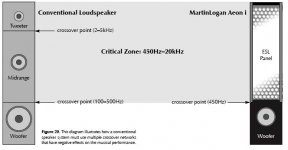
In order to use multiple drivers, a crossover network is enlisted to attempt a division of the complex musical signal into the separate pieces (usually highs, mids, and lows) thateach specific driver was designed to handle. Unfortunately, due to the phase relationships that occur within all crossover
networks and during the acoustical recombination process, nonlinearities and severe degradation of the music signal take place in the ear’s most critical zone (see figure 20).
The Aeon i’s electrostatic transducer can single-handedlyreproduce all frequencies above 450 Hz simultaneously. You have in one transducer the ability to handle in elegant simplicity the critical frequencies above 450 Hz.
The crossover phase aberrations that are associated with traditional tweeter, midrange, and woofer systems are eliminated. The result is a dramatic improvement in imaging and staging performance due to the minutely accurate phase relationship of the full-range panel wave launch.
(See attachment)
Figure 20. This diagram illustrates how a conventional speaker system must use multiple crossover networks that have negative effects on the musical performance.
Extracts from the Martin Logan's operators manual of the AEON i
=============================================
Full Range Operation
The most significant advantage of Martin Logan’s exclusive transducer technology reveals itself when you look at examples of other loudspeaker products on the market today.
The Aeon i uses no crossover networks above 450 Hz because they are not needed. The Aeon i consists of a single, seamless electrostatic membrane reproducing all frequencies above 450 Hz simultaneously. How is this possible?
First we must understand that music is not composed of separate high, mid and low frequency pieces. In fact, music is comprised of a single complex waveform with allfrequencies interacting simultaneously.
The electrostatic transducer of the Aeon i essentially acts as an exact opposite of the microphones used to record the original event. A microphone, which is a single working element, transforms acoustic energy into an electrical signal that can be amplified or preserved by some type of storage media. The Aeon i’s electrostatic transducer transforms electrical energy from your amplifier into acoustical energy.
Due to the limitations of electromagnetic drivers, no single unit can reproduce the full range of frequencies. Instead, these drivers must be designed to operate within a narrow, fixed bandwidth of the frequency range, and then combined electrically so that the sum of the parts equals the total signal. While nice in theory, we must deal with real-world conditions.
In order to use multiple drivers, a crossover network is enlisted to attempt a division of the complex musical signal into the separate pieces (usually highs, mids, and lows) thateach specific driver was designed to handle. Unfortunately, due to the phase relationships that occur within all crossover
networks and during the acoustical recombination process, nonlinearities and severe degradation of the music signal take place in the ear’s most critical zone (see figure 20).
The Aeon i’s electrostatic transducer can single-handedlyreproduce all frequencies above 450 Hz simultaneously. You have in one transducer the ability to handle in elegant simplicity the critical frequencies above 450 Hz.
The crossover phase aberrations that are associated with traditional tweeter, midrange, and woofer systems are eliminated. The result is a dramatic improvement in imaging and staging performance due to the minutely accurate phase relationship of the full-range panel wave launch.
(See attachment)
Figure 20. This diagram illustrates how a conventional speaker system must use multiple crossover networks that have negative effects on the musical performance.
Attachments
Guides before you start Building-P3
Extracts from the Martin Logan's operators manual of the AEON i
=============================================
Specifications
The Aeon i hybrid speaker system consists of a broad-range single-element electrostatic transducer integrated with a quick-response woofer. This approach takes advantage of the benefits that both technologies have to offer. Dispersion is a controlled 30 degrees, achieved by curving the electrostatic transducer element—an elegantly simple solution.
System Frequency Response
43–22,000 Hz ± 3 dB
Dispersion
Horizontal: 30 Degrees
Vertical: 37 inch (94 cm) line source
NAC™ enhanced sound field
Sensitivity
90 dB/2.83 volts/meter
Impedance
Nominal: 4 ohms
Minimum: 1.1 ohms @ 20 kHz
Crossover Frequency
450 Hz
Components
Custom-wound audio transformer, air core coils,
polypropylene capacitors
NAC Driver
1” (2.5cm) silk dome
Woofer Type
8" high excursion, aluminum cone with extended
throw driver assembly, non-resonance chamber format
Power Handling
200 watts per channel
Recommended Amplifier Power
80–200 watts per channel
Weight
55.5 lbs. each (25.2 kg)
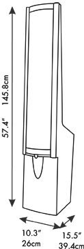
Size
10.25 inches W °— 15.5 inches D °— 57.4 inches H
(26 cm W °— 39.4 cm D °— 145.8 cm H)
Extracts from the Martin Logan's operators manual of the AEON i
=============================================
Specifications
The Aeon i hybrid speaker system consists of a broad-range single-element electrostatic transducer integrated with a quick-response woofer. This approach takes advantage of the benefits that both technologies have to offer. Dispersion is a controlled 30 degrees, achieved by curving the electrostatic transducer element—an elegantly simple solution.
System Frequency Response
43–22,000 Hz ± 3 dB
Dispersion
Horizontal: 30 Degrees
Vertical: 37 inch (94 cm) line source
NAC™ enhanced sound field
Sensitivity
90 dB/2.83 volts/meter
Impedance
Nominal: 4 ohms
Minimum: 1.1 ohms @ 20 kHz
Crossover Frequency
450 Hz
Components
Custom-wound audio transformer, air core coils,
polypropylene capacitors
NAC Driver
1” (2.5cm) silk dome
Woofer Type
8" high excursion, aluminum cone with extended
throw driver assembly, non-resonance chamber format
Power Handling
200 watts per channel
Recommended Amplifier Power
80–200 watts per channel
Weight
55.5 lbs. each (25.2 kg)
Size
10.25 inches W °— 15.5 inches D °— 57.4 inches H
(26 cm W °— 39.4 cm D °— 145.8 cm H)
Attachments
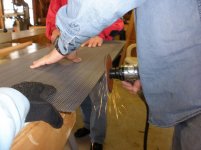
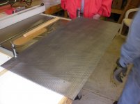

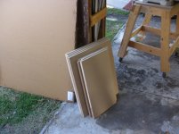
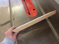
i was doing my best to take pics during cutting, grinding, etc. it was getting late and did not have opportunity to take close ups the edges, they are all smooth as well as the long and short ends, no protruding "points" sticking out whats so ever.
i have some test pieces now, so the next is to spray and i post pics as well thickness. Charlie, just got off the phone with parts express, bo info, best to call 3m directly, if some gets a chance, parts express part #082-180. thats what I have. Trying to make sure its none conductive, Charlie allready has a post on this. Thanks
i have some test pieces now, so the next is to spray and i post pics as well thickness. Charlie, just got off the phone with parts express, bo info, best to call 3m directly, if some gets a chance, parts express part #082-180. thats what I have. Trying to make sure its none conductive, Charlie allready has a post on this. Thanks
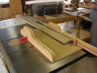
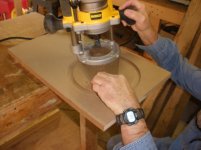
the handy work is Charlie, a nice plunge router and there you go, makes one heck of a mess, never heard him cuss so much, all good times!!! toomorow, hopefully, try the sprayed panels!! customer came in, needs the truck bed sprayed! so i will take pics and post
> test #1 rhino @ 180 F" @ 2000 psi @ 3 feet, or metric. this will be neat.
later, look forward to any coments.
just have to thank Charlie and Ger, as no one else has posted more helpful advice and just good advice, much appreciated. Mav
> test #1 rhino @ 180 F" @ 2000 psi @ 3 feet, or metric. this will be neat.
later, look forward to any coments.
just have to thank Charlie and Ger, as no one else has posted more helpful advice and just good advice, much appreciated. Mav

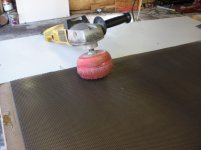
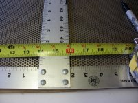
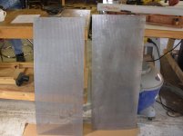
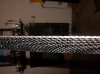
IT WORKED IT WORKED!!!!!!! check oout the pics, rhino'ed a test panel today, finally, 16.1 mill consistantly +-.5 mill on 40" 51% open area stator. no clogs, perfect. I can now spray my panels and be finished with this obstacle and it wont cost me a dime. its flexable, bent one end in half, no cracks or tears. check it out.
Attachments
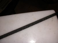
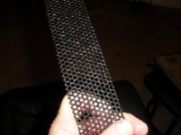
IT WORKED IT WORKED!!!!!!! check oout the pics, rhino'ed a test panel today, finally, 16.1 mill consistantly +-.5 mill on 40" 51% open area stator. no clogs, perfect. I can now spray my panels and be finished with this obstacle and it wont cost me a dime. its flexable, bent one end in half, no cracks or tears. check it out.
Hey, it looks OK. If you like it, I like it. Did you hang them up to spray them? I hung mine with weights attached so they wouldn't swing while I sprayed them. I would not go any thicker, though.
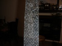
no i did not hang it, it was the first test, so i just propped it against something and shot it, some of what you see is over spray as we had a long bed truck at the time that was getting done too. thats why there are "speckles" and probally why the thickness was a little more on the holes, that stuff sticks to anything. i wish i could video, but i have to wear a haz mat suit, gloves, face mask and all, and dont wanna mess up my camera. I still have three more test pieces, then i will bring them to you, Mr. Charlie. I wish i post a high res here, but the rules are rules and i do not wish to break them.
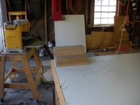
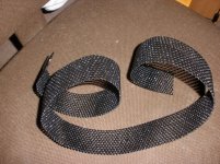
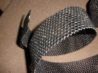
that was sprayed about six feet away, i put a marker on the floor and will see what five feet looks like, and so on. the machine was set @ 2250psi, so closer might be better, as the material will blast right through the stator and give a better result. i have been waiting for this and now another try as soon as i can.
so, i have it written down, one spray pass @ 6' and it looks nice, gonna try and do better next time.
on another note, i can only measure the outside or surface, i do not know how much it effected the hole diameter, but it looks consistant.
another thing, now both sides are smooth, does that make a diffence? it is hard to tell the punched side from the back flat side. its just the surface is so smooth, which i figured would also benifit should the diagphram come in contact.
resonace, i used a quarter and tapped it, it pinged. now you can throw it on concrete and it does not make a sound, it bounced without pinging or any noise for that matter.
thats it, for now.
Apparently there is this thing called aerogel. Its supposedly lighter than air.
I love mylar, it is super strong. Wine boxes have a baggie inside of them made of mylar, 2 very thin layers of it. Inflate it but blowing into the tap (when empty of course) and you can stand on it and it wont blow.
You also can clean one out with hot water (pulling on the tap makes it come off) and fold and carry one in your backpack. Now if you're a biker, you run out of gas, you can just walk to the gas stattion, get a gallon in it, fill up and ride on. No need to push the bike there.
Cool.
Srinath.
- Status
- This old topic is closed. If you want to reopen this topic, contact a moderator using the "Report Post" button.
- Home
- Loudspeakers
- Planars & Exotics
- Material for ESL