Hi Sync,
There was never a GB, just some files to make boards floating around.
I don't know if there is any interest in these enough, but if someone wants to run a GB on this, they are more than welcome for the stuff I have put forward. Ask the designer of any board files if you want to use them. I can't give permission for them.
-Chris
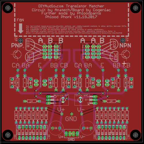
Here's my latest revision. You have my permission. My board is a fork of Anatech's schematic and Cogeniac's original PCB design, and I guess he'd approve as well, but don't take my word for it.
Actually, it would be cool if we just made it available open-source. It would need to be converted to KiCad.
Actually, it would be cool if we just made it available open-source. It would need to be converted to KiCad.
Oops! There was an airwire in that last version, on the emitter of the NPN sockets. Easily fixed with a bodge wire if you've ordered boards from that file. (v2017.11.19)
It's fixed.
Here's the latest version.
It's fixed.
Here's the latest version.
Hey everyone, how about we take this project open-source? It seems like it would be really useful to people around the world, not just to the DIY Audio scene.
I've been looking for a reason to learn GitHub, and this would be the perfect project. We can put Eagle files up on Github, and even though Eagle is not open-source, the project can still be. I'd be willing to do a KiCad version if people think that's really essential.
I've been looking for a reason to learn GitHub, and this would be the perfect project. We can put Eagle files up on Github, and even though Eagle is not open-source, the project can still be. I'd be willing to do a KiCad version if people think that's really essential.
From a purely selfish point of view I'd love to see a Kicad version since I would rather not have to learn Eagle after fighting my way through Kicad. But it is certainly not essential that you do that. I'm happy to learn from the masters here no matter how they choose to teach.Hey everyone, how about we take this project open-source? It seems like it would be really useful to people around the world, not just to the DIY Audio scene.
I've been looking for a reason to learn GitHub, and this would be the perfect project. We can put Eagle files up on Github, and even though Eagle is not open-source, the project can still be. I'd be willing to do a KiCad version if people think that's really essential.
Hi Spike,
Yes, I stick them on a common heat sink that carries 4 at a time. I pre-sort them using a Heathkit IT-18 (which is pretty accurate actually), then run the group up to a higher temperature and let them stabilise. I measure the collector currents across a set of matched 1R0 resistors. I have another jig for Mosfets and do the same thing with them, but using a different transistor checker (B&K 530 - not so accurate but I just look for the same needle position). It should be noted that I have the transistors lined up on the bench for 1/2 hour minimum before attempting to take any measurements. I'm very careful not to breathe on them, or touch them. I just connect the leads to the parts and take a reading.
Temperature is a really, really critical variable when measuring any aspect of transistors. Power or signal, they are all very sensitive to temperature. Either beta or transconductance is the key characteristic that we normally need. Measuring E-B voltages can be important for some applications, but for an audio amplifier you would normally be going after a gain figure of merit. Although, for Mosfets you might want to take the turn-on voltage. J-Fets are more interesting where you would measure Idss and Vgs(off), or any depletion mode power Mosfet.
No matter what you are measuring, take pains to get all the devices at the exact same temperature (or as close to the same as is reasonably possible). If you fail to do this, you will never get a matched set of parts except by complete fluke.
-Chris
Rod Elliot has an excellent article about the matching of power devices.
Matching Power and Driver Transistors
Matching Power and Driver Transistors
I've built up my latest fork of the board and here it is.

And of course, I've since made a few tiny revisions—just some text and a couple of hole positions. Here are the latest Eagle and Gerber files if you want to get your own boards made, or want to modify the design.
And of course, I've since made a few tiny revisions—just some text and a couple of hole positions. Here are the latest Eagle and Gerber files if you want to get your own boards made, or want to modify the design.
I gave the article a quick scan. I couldn't help but notice that he is in conflict with Motorola / On-Semi with his comments about the benefits of matching outputs and entire output stages. I have in fact measured lower distortion when these things are properly matched. That would support the view that the On-Semi data sheets state. In other words, my own empirical evidence contradicts what Rod is saying. I guess itis possible that if he didn't match devices closely enough, he would never have seen an improvement. That's too bad really.
He is right on the money regarding the temperature of these devices when trying to match them.
-Chris
Edit:
Man, that just blows me away!
That would never work with smt's!
He is right on the money regarding the temperature of these devices when trying to match them.
-Chris
Edit:
Man, that just blows me away!
That would never work with smt's!
Typo. :/ Here's the correct link to download Gerbers and Eagles of the latest board.
Dropbox - DIYAudioTransistorMatcher_Phlood_v2018.01.07.zip
Dropbox - DIYAudioTransistorMatcher_Phlood_v2018.01.07.zip
Hi Chris:
Is the 1R0 = to 1.0 ohm or 10 ohm?
As the 1k0 = 1,000 Ohm.
or the 5k6 = 5600 Ohm.
I'm thinking I'd probably go with the 10 Ohm matched to .1 or .01 percent. for four of them with the TO-3 devices.
10 Ohm would give me an extra decimal place with a restricted readout meter. When you get used to 5-1/2 or 6-1/2 digits a regular hand held is kinda short. So instead of .052 Volts/1 Ohm = 52mA.
an indication .522 Volts10 Ohms = 52.2mA.
Extra precision all around.
I think I've got it.
Cheers,
Last edited:
Sync,
put your 10r resistors in series. Use either solder joints or screwed terminals to get reliable joints.
Pass 19mA through the string of resistors. Each resistor will drop ~190mV
and 10 of them will need a supply voltage of 1.9Vdc
you can use a 3.5 digit DMM set to 199.9mVdc and record each Vdrop. go around the string again and record each Vdrop and repeat again.
You now have three readings for each resistor. you may find that the first is consistently different from the 2nd and 3rd. if this is the case then discard the 1st and average the 2nd & 3rd.
It is important to measure with the probes set a fixed distance apart. Lead resistance begins to affect results, even with copper lead outs.
Now select matches of Vdrop and store them away as matched sets. You can get +-0.05% using a 3.5digit DMM. With care and extended testing you can get better than +-0.026% using 3.5digits.
If you have more resolution you can do even better, but your methods need to be exemplary to get below +-0.01%
I chose 19mA to limit power dissipation (3.6mW through 10r) and this low current nearly eliminates the effects of tempco from your measurements
If you have an accurate 100r, say 0.1% or 0.01%, then you can compare the 10 off 10r resistor string to the 100r ref and get a correction factor to apply to all your 10r. Reduce your test current for this comparison, since the 100r is dissipating ten times the power.
Last edited:
Hi Sync,
Just go ahead and buy the 0.1% parts. They will be more stable than the selected 1% parts and the time required to match them is more than worth the difference in price. Keep in mind that your matches are going to be on the order of 1%, maybe half that, so a 0.01% match is wasted. Besides, the connector interface to the parts under test may exceed even the 0.1% tolerance on the resistors.
I use a meter that is 7 1/2 digit internally (HP 3457A) in a Kelvin connection (four wire ohms). The 34401A will have the resolution, but the ohms function isn't nearly as accurate as the basic DC voltage accuracy. Look up the specs on your meter to be more certain of direct accuracy. However, the meter will be very accurate for relative measurements. The 34401A also has a ratio mode. You can connect a resistor to the sense terminals and the others can test resistors one by one giving you the ratio between them. Pretty slick eh?
-Chris
1R0 = 1.0 ohms, the rest are correct.Is the 1R0 = to 1.0 ohm or 10 ohm?
As the 1k0 = 1,000 Ohm.
or the 5k6 = 5600 Ohm.
Just go ahead and buy the 0.1% parts. They will be more stable than the selected 1% parts and the time required to match them is more than worth the difference in price. Keep in mind that your matches are going to be on the order of 1%, maybe half that, so a 0.01% match is wasted. Besides, the connector interface to the parts under test may exceed even the 0.1% tolerance on the resistors.
I use a meter that is 7 1/2 digit internally (HP 3457A) in a Kelvin connection (four wire ohms). The 34401A will have the resolution, but the ohms function isn't nearly as accurate as the basic DC voltage accuracy. Look up the specs on your meter to be more certain of direct accuracy. However, the meter will be very accurate for relative measurements. The 34401A also has a ratio mode. You can connect a resistor to the sense terminals and the others can test resistors one by one giving you the ratio between them. Pretty slick eh?
-Chris
Interesting. Thanks Andrew and Chris.
I have both those meters Chris, the HP3457a is down. The HP34401As work fine. On the 34401A, I got you I think. Put a resistor on sense becoming the "standard". Then I need to figure how to supply the same DC Volts to it and then "test" the others in series as Andrew states. So I'll get a differential reading.
Andrew, the correction factor, the 10 ohm x 10 string, compared to 100 ohm then factor would be X, and the correction factor is X/10 for each 10 ohm resistor?
I get it. And this can be applied to any variety of resistors and types. I like it. Anything else? And I know just how to solder them up, tiny bits of solder at the resistor lead ends in WVW pattern. I've seen that and now I understand it.
Cheers,
Hi Sync,
What's wrong with the 3457A?
Putting the resistors in series ensures that each is passing the same current. If the voltage drops are small enough, put your 34401A into high input Z mode (10 Gohm I think) to reduce circuit loading. Do this and the math will work out.
-Chris
What's wrong with the 3457A?
Putting the resistors in series ensures that each is passing the same current. If the voltage drops are small enough, put your 34401A into high input Z mode (10 Gohm I think) to reduce circuit loading. Do this and the math will work out.
-Chris
- Home
- Design & Build
- Equipment & Tools
- Matching transistors & measuring the results