Hi Andrew,
That is certainly one way of going about this. I guess you have to be careful of loading if your resistances are very high, and possibly noise pickup. While this is works for relative readings, the errors would be larger for determining the actual values. The test current factor would be the main source of errors.
We do use a variation on the theme to accurately measure current in a 4 ~ 20 mA current loop. A 250R precision resistor would be put in series with the loop and the voltage across read out. This only works because a lab's standard resistance is extremely close tolerance, and is also certified every year.
I think I would consider this method one that has unknown sources of errors, and so the uncertainty would be higher.
If nothing else, a hobbyist should own at least one accurate meter. One made by Fluke or Keysight / Agilent / HP. Extech (for example) is not reliable and does not hold it's calibration well. I only mention them because they make claims to being as good as Fluke or Keysight. They aren't.
-Chris
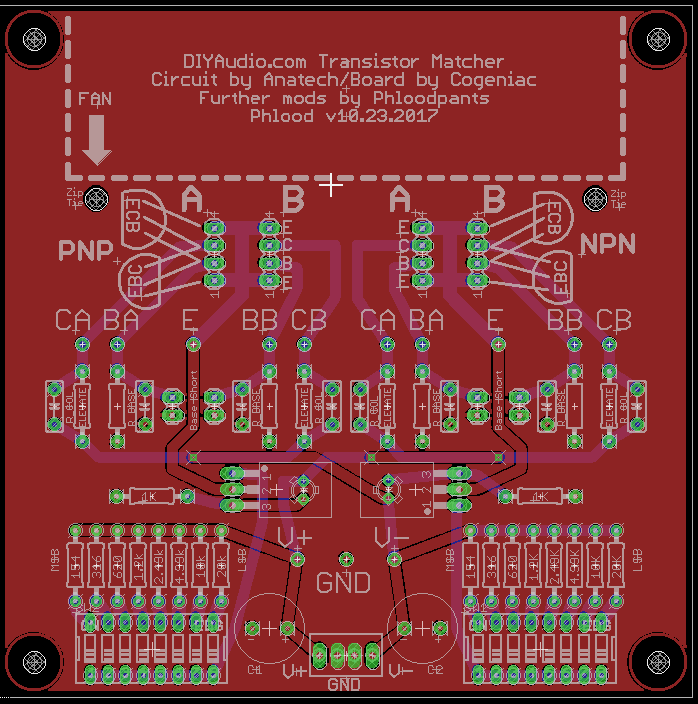
Here's my latest fork of the DIYAudio Matcher Board.
DIYAUDIO Transistor Matcher Gerbers and Eagles
I went a little nuts with the symmetry, to the point of making the collector current carrying traces the same length. I've added jumpers to short the base resistors, or optionally to measure base current. Tidied up the schematic. ...and a bunch of other fine details.
I haven't actually built or tested this new version, but the one I did before it was pretty much the same. I've just moved things around, so I'm 99% confident it'll work.
Hi Phloodpants,
You should contact the store and offer your files to them. They won't include it for a little while as there are a lot of things going on in this site as we prepare for a new platform. Once that and Burning Amp are both done, they will have time to consider new products.
About the fan. I have waited on the sidelines on this topic. I do not recommend using a fan and stress that the two transistors need to be at the same case temperature. That means in thermal contact with foam to block convection currents and a box to kill air currents that can cause the two parts to have differing temperatures.
Tail current should be set at the applications target current (normally 1 ~ 2 mA), but I find matching is a little faster when the tail current is set to 3 mA. Might be faster at higher currents but I want to keep self heating down to normal levels. There is a compromise between how fast you can go and getting good matches.
Signs of having a good match. I just worked on a Marantz 2325 restoration / improvement yesterday. The new matched pairs placed the DC offset pots in a centered position. For amplifiers lacking this adjustment, a good match will result in the output voltage with minimal DC offset. There are some amplifiers where an offset is designed in. Never understood that, but a good pair will result in the DC offset being what you can calculate from the schematic and knowledge of transistor betas and tail current. In other words, the amplifier is "happy".
-Chris
There, I fixed it! You can have it either way. I added a second row of pads for the DUTs, so you can choose between using the widely-spaced pads to allow airflow for the fan-based temperature equalization method, or the closely-spaced pads to allow physical contact for the thermal-bonding method.
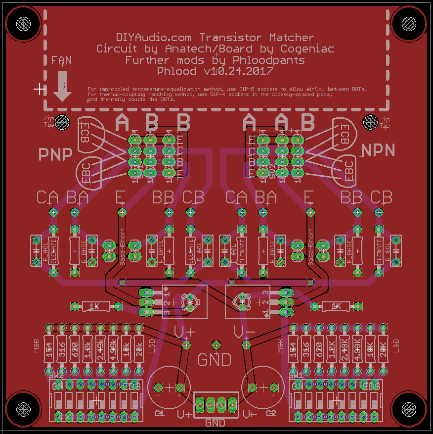
I'm interested in investigating this matter further, and I'll be doing some more tests comparing the methods. Meanwhile, the board allows you to choose your own adventure.
Download Eagles and Gerbers here.
I'm interested in investigating this matter further, and I'll be doing some more tests comparing the methods. Meanwhile, the board allows you to choose your own adventure.
Download Eagles and Gerbers here.
Hi phloodpants,
Any chance you could put an idiots guide to using the matcher up?
Thanks
Yeah, once we sort out some of these details...
OK, the data is in!
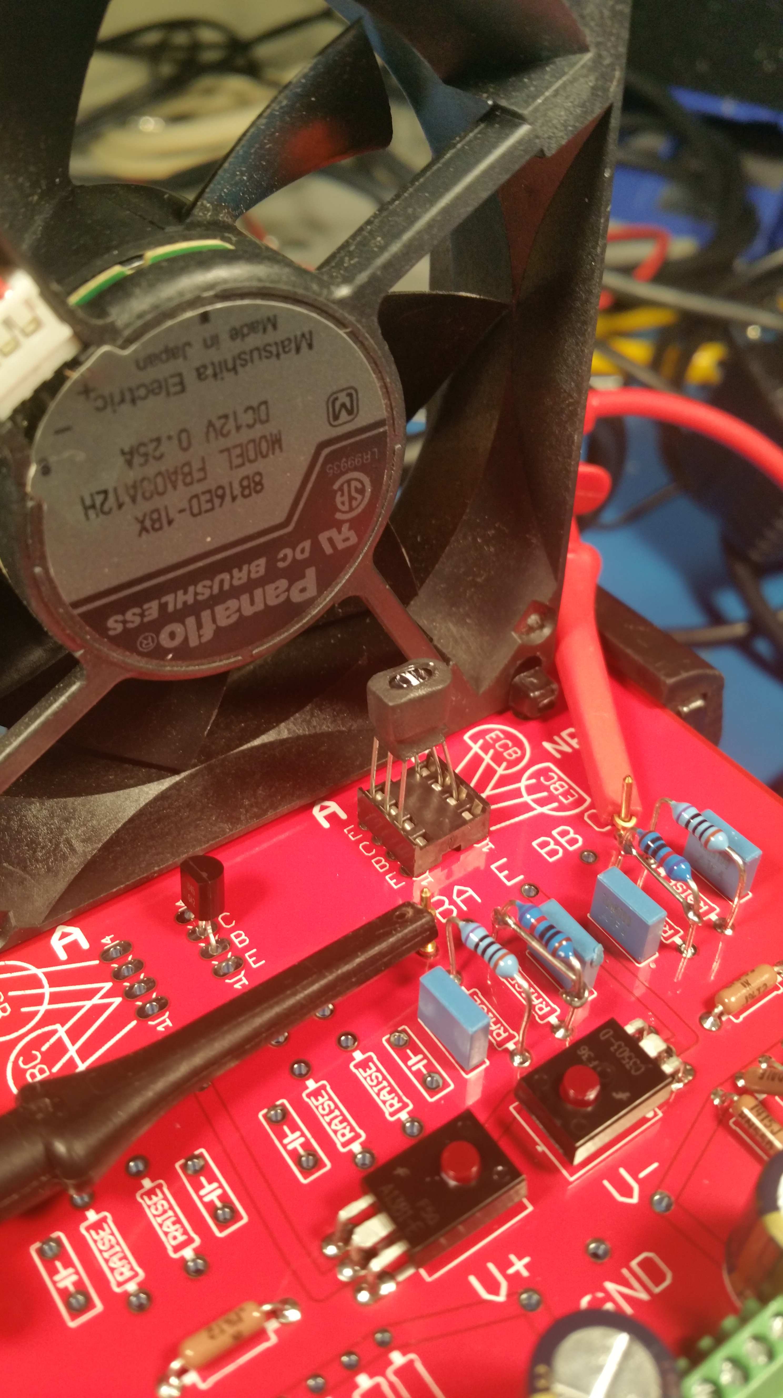
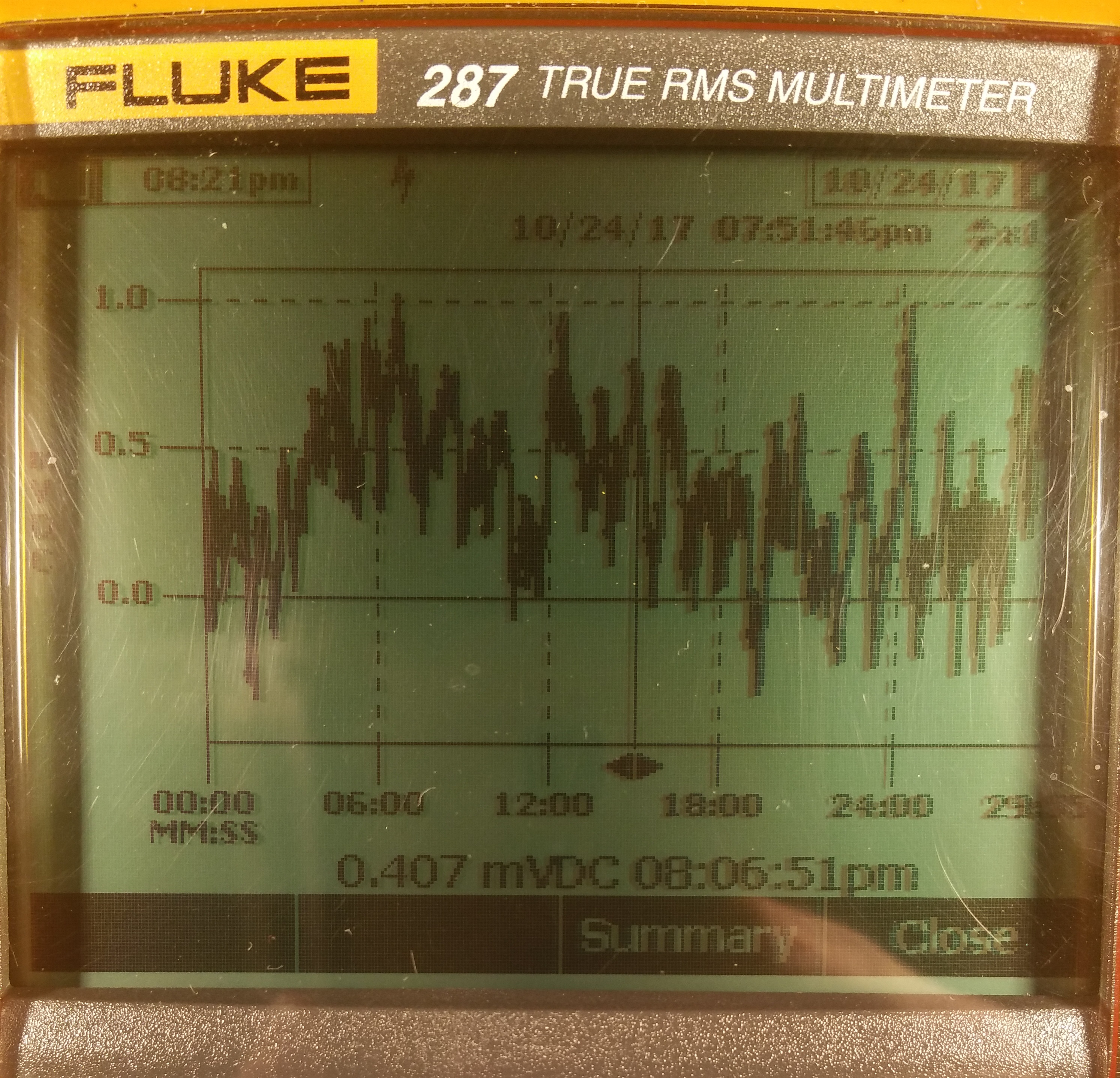
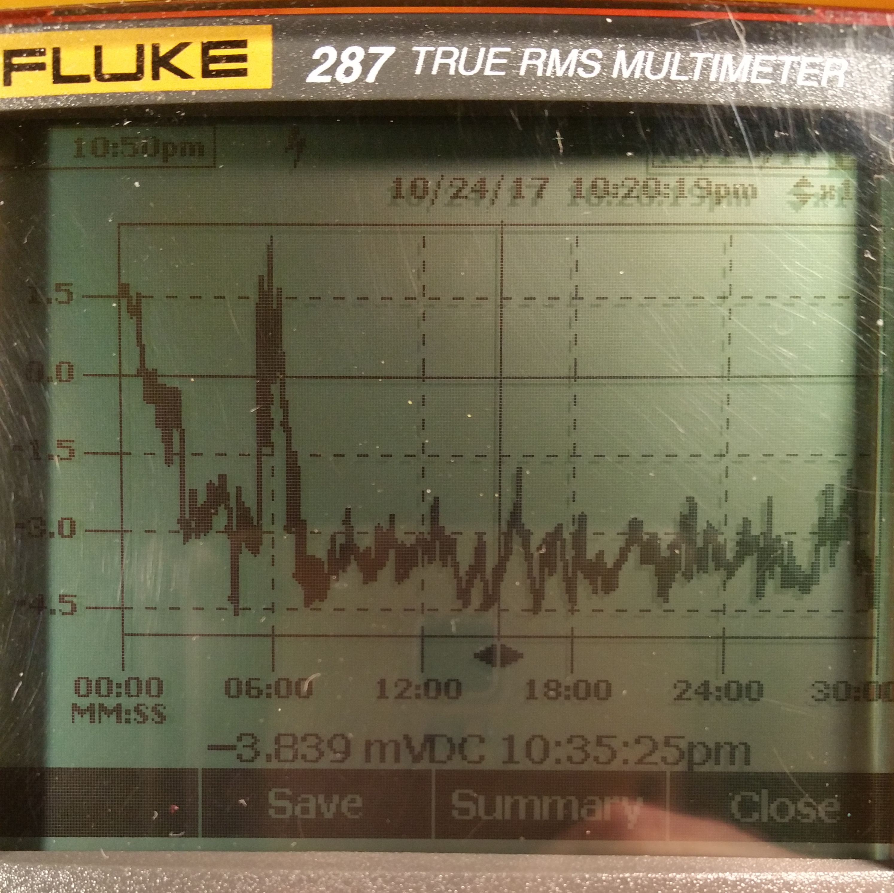
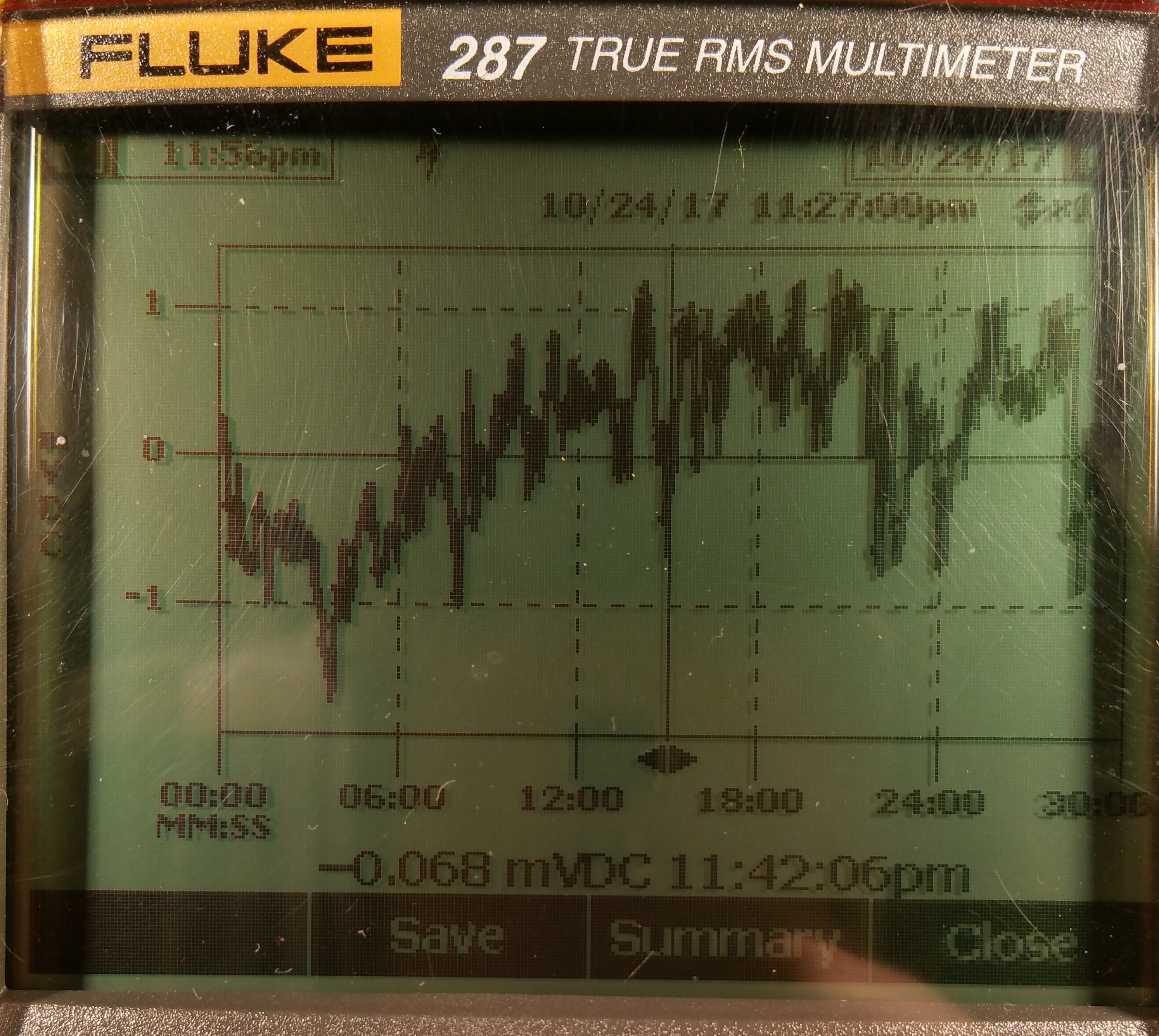
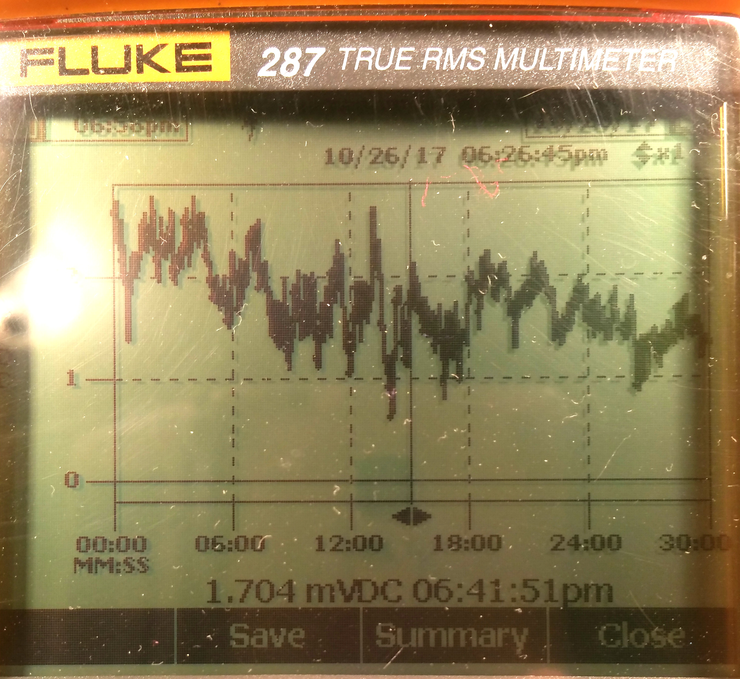
Three matched sets of 2SC1845 were found using the "Fan method". A data-logging multimeter was used to graph the voltage delta between devices over a 30-minute period; first using the fan method, and then thermally bonded.
The "Fan Method":
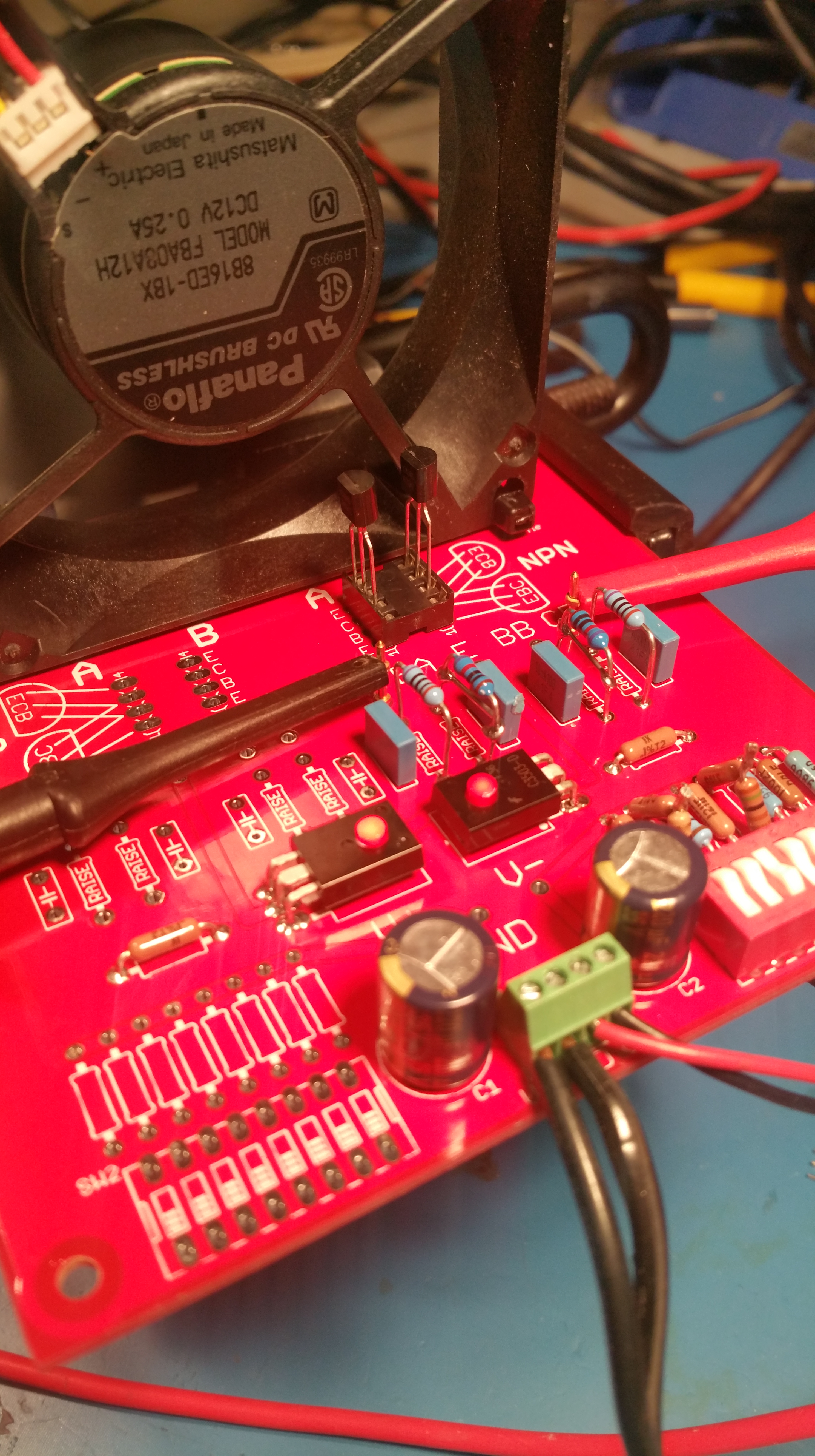
The "Thermally Bonded Method": (Fan stopped, transistors smeared with heatsink compound and shrink-wrapped.)
Devices were allowed to cool to room temperature before each run. Conveniently, a 1mV change represents 1%. (100mV across 100R collector resistor, and 1ma collector current.)
I don't have a data-link thingy for my Fluke, so I had to take pictures of the screen.
Pair #1, Fan Method
Pair #1, Thermally Bonded Method
Pair #2, Fan Method
Pair #2, Thermally Bonded Method

Pair #3, Fan Method

Pair #3, Thermally Bonded Method
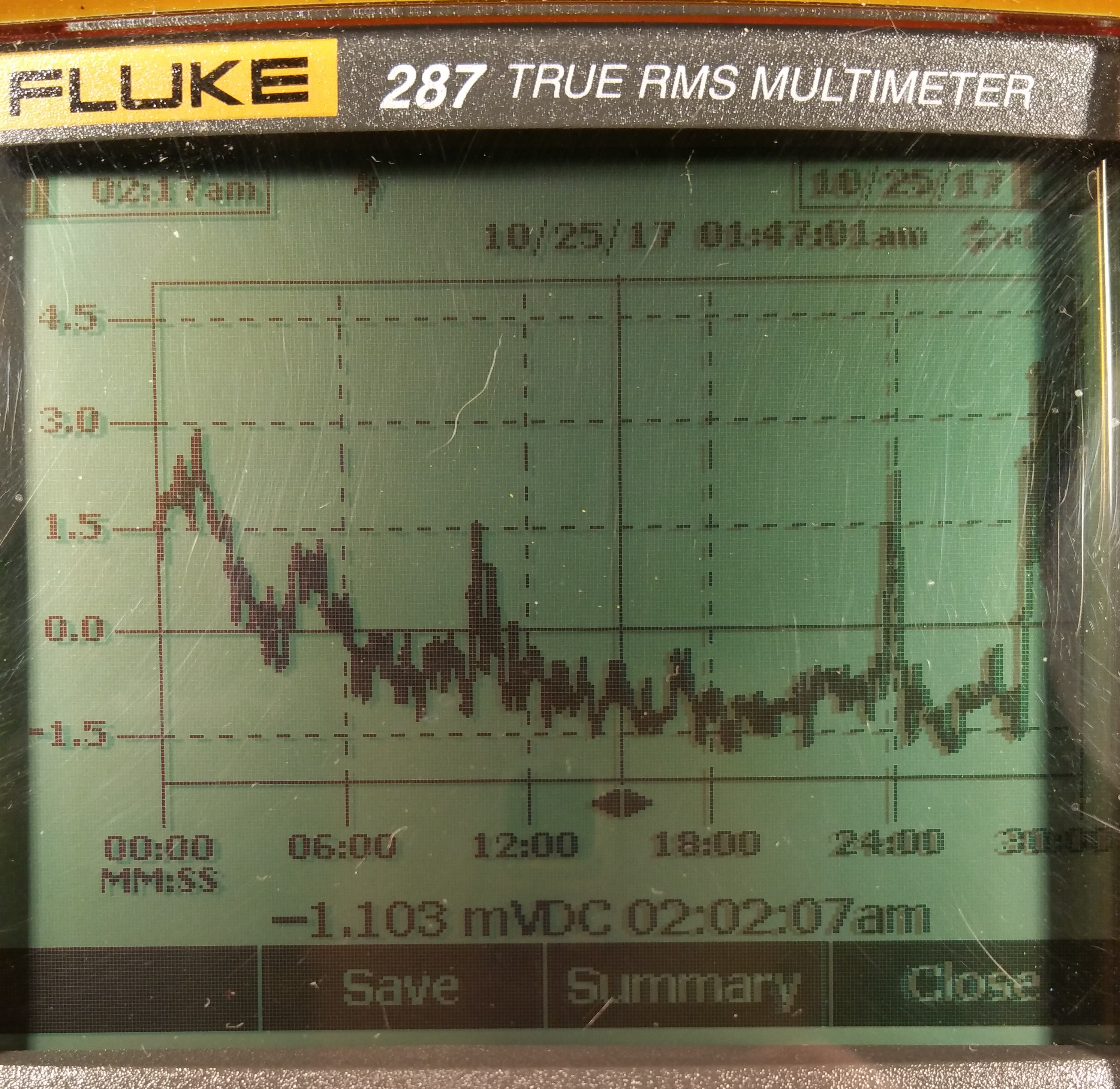
Pair #1 showed the most variance between the two methods; about 3.5%. Pair #2 is about 1.5%, and pair #3, on average, appears to be about the same either way.
I'm not exactly sure what to make of this. It's not a huge variance in any case.
The thermally bonded pairs seem to take a consistent 6 minutes to stabilize, whereas the fan ones seem to settle almost immediately—most of the time—but sometimes seem to need that 6 minutes settling time as well.
I think both methods do a good job of equalizing the temperatures between devices. The fan-cooled pairs will be operating at a lower temperature than the thermally bonded pairs, and there does appear to be some variance in the tracking of their beta vs. temperature curves. The thermally-bonded pairs will run warmer, more like how they will actually be used. Actually, they will run hotter in an hot equipment case. Anatech was suggesting foam around the devices and that should get them closer to actual operating temperature. Maybe that would make another few percent's difference.
Perhaps a hybrid approach is in order. Using the fan, most of the pairs settle in less than 30 seconds. If one is sorting through hundreds of transistors, using a single one as the reference, and binning them by their voltage delta from the reference... you don't need precision at that stage. You just need little piles of candidates that can be verified with the more time-consuming thermally-bonded method.
And perhaps the best of both worlds, but messy... Submerge the whole thing in mineral oil that is heated to the same temperature as the devices actually operate at inside the amplifier case, with a fan to circulate the liquid. That should hold the DUTs at an extremely consistent temperature, and they would settle almost immediately. Matching would be quick and precise.
Three matched sets of 2SC1845 were found using the "Fan method". A data-logging multimeter was used to graph the voltage delta between devices over a 30-minute period; first using the fan method, and then thermally bonded.
The "Fan Method":
The "Thermally Bonded Method": (Fan stopped, transistors smeared with heatsink compound and shrink-wrapped.)
Devices were allowed to cool to room temperature before each run. Conveniently, a 1mV change represents 1%. (100mV across 100R collector resistor, and 1ma collector current.)
I don't have a data-link thingy for my Fluke, so I had to take pictures of the screen.
Pair #1, Fan Method
Pair #1, Thermally Bonded Method
Pair #2, Fan Method
Pair #2, Thermally Bonded Method
Pair #3, Fan Method
Pair #3, Thermally Bonded Method
Pair #1 showed the most variance between the two methods; about 3.5%. Pair #2 is about 1.5%, and pair #3, on average, appears to be about the same either way.
I'm not exactly sure what to make of this. It's not a huge variance in any case.
The thermally bonded pairs seem to take a consistent 6 minutes to stabilize, whereas the fan ones seem to settle almost immediately—most of the time—but sometimes seem to need that 6 minutes settling time as well.
I think both methods do a good job of equalizing the temperatures between devices. The fan-cooled pairs will be operating at a lower temperature than the thermally bonded pairs, and there does appear to be some variance in the tracking of their beta vs. temperature curves. The thermally-bonded pairs will run warmer, more like how they will actually be used. Actually, they will run hotter in an hot equipment case. Anatech was suggesting foam around the devices and that should get them closer to actual operating temperature. Maybe that would make another few percent's difference.
Perhaps a hybrid approach is in order. Using the fan, most of the pairs settle in less than 30 seconds. If one is sorting through hundreds of transistors, using a single one as the reference, and binning them by their voltage delta from the reference... you don't need precision at that stage. You just need little piles of candidates that can be verified with the more time-consuming thermally-bonded method.
And perhaps the best of both worlds, but messy... Submerge the whole thing in mineral oil that is heated to the same temperature as the devices actually operate at inside the amplifier case, with a fan to circulate the liquid. That should hold the DUTs at an extremely consistent temperature, and they would settle almost immediately. Matching would be quick and precise.
Last edited:
Yeah, I think we're wading into really murky waters here. I think the jig is actually far more precise than the transistors can ever be. I was wondering about how much the transistors drift from each other with temperature, and did a simple experiment: This graph shows Pair #3 using the thermally bonded method and no fan. A thermocouple was attached to the transistors, reading about 30C. For the first 5 minutes, all is well behaved as before. After 5 minutes, I heated the transistors with a 60W desk lamp placed about 6 inches away. The temperature rose slowly to 80C, and here's what happened. Sorry I don't have a graph of the actual temperature.
The delta goes positive just above room temperature, and then negative again at higher temperatures. With this particular pair of transistors—apparently good matches—it seems they would vary with heat at least 12% inside the hot case of an actual amplifier!
So really, if you want super precise matches, they would actually need to be done at the same temperature as they are in the amp, and that temperature will vary lot in use. And you would need to characterize their delta versus temperature, to find pairs that track each other.
This is why regulated-temperature ovens are used to heat critical circuitry to an even temperature in high-precision oscillators and such.
A lot of the variance seen in the charts I posted earlier could simply be due to changes in room temperature and air circulation.
An externally hosted image should be here but it was not working when we last tested it.
The delta goes positive just above room temperature, and then negative again at higher temperatures. With this particular pair of transistors—apparently good matches—it seems they would vary with heat at least 12% inside the hot case of an actual amplifier!
So really, if you want super precise matches, they would actually need to be done at the same temperature as they are in the amp, and that temperature will vary lot in use. And you would need to characterize their delta versus temperature, to find pairs that track each other.
This is why regulated-temperature ovens are used to heat critical circuitry to an even temperature in high-precision oscillators and such.
A lot of the variance seen in the charts I posted earlier could simply be due to changes in room temperature and air circulation.
Last edited:
Hi Phloodpants,
That's very good work. My observations covered very similar testing to your own, carried out over many years. Once a pair is coupled and held together, they will track much more evenly over temperature. This can be seen as testing when the amplifier (in this case) is first turned on and 1/2 an hour later after everything is warmed up. The DC offset usually remains the same with a good pair. It will deviate a fair bit with a mismatched pair of transistors.
My experience has shown me that there is value in putting a touch of heat sink grease between them and then using heat shrink tubing to hold them in position. You will see this method used in some really well made older equipment, like the higher end Marantz models. They actually used grease and heat shrink as well. Time consuming on a production line. It must have been technically worthwhile. It is from my studies.
I think that a group buy might be the way to go since the store will not be in a position to include any new products in the short term. From what I have seen, these boards are easily high enough quality and would be a great addition to our members who work with diff pairs.
-Chris
So, here's a couple of intentionally poor matches. They were off by about 9% with the fan method, and about 28-30C to start with. I then applied the lamp and let them warm up to 80C again. It's kind of interesting that they had the same variance range as the good matches, about 20% peak to peak change with heat. At one point, they almost match!
The curve of the change with heat is not predictable, so matching at any one particular temperature is problematic. All this suggests an alternative matching method, although it would be pretty labor-intensive. What's really needed is a plot of voltage across the collector resistors versus temperature, at a certain operating current like 1mA or whatever. You could match plots on the computer to find devices where the lines track with temperature. It seems there is quite a lot of random variation, but I'm sure pairs could be found that track closer than the +/- 20% I've found with the few pairs I've tried.
A different kind of matching jig could be built to plot these data, with provision for just one transistor, and utilizing a precision regulated current source for measurement repeat-ability, with a thermocouple attached to the inside of some kind of metal shroud or helmet to go over the transistor being tested. A small power resistor can be attached to the transistor helmet, to apply heat to the transistor, and the voltage versus temperature plotted. These plots would then be matched on the computer screen to find the ones whose curves match the closest.
Maybe this is more precision than needed.
An externally hosted image should be here but it was not working when we last tested it.
The curve of the change with heat is not predictable, so matching at any one particular temperature is problematic. All this suggests an alternative matching method, although it would be pretty labor-intensive. What's really needed is a plot of voltage across the collector resistors versus temperature, at a certain operating current like 1mA or whatever. You could match plots on the computer to find devices where the lines track with temperature. It seems there is quite a lot of random variation, but I'm sure pairs could be found that track closer than the +/- 20% I've found with the few pairs I've tried.
A different kind of matching jig could be built to plot these data, with provision for just one transistor, and utilizing a precision regulated current source for measurement repeat-ability, with a thermocouple attached to the inside of some kind of metal shroud or helmet to go over the transistor being tested. A small power resistor can be attached to the transistor helmet, to apply heat to the transistor, and the voltage versus temperature plotted. These plots would then be matched on the computer screen to find the ones whose curves match the closest.
Maybe this is more precision than needed.
Hi Phloodpants,
Just lost a big post. Grrr... I hate Windows!
Anyway, the only valid way to do this is to roughly replicate the conditions a diff pair will see in actual use. That's in a decently designed circuit of course! So tie the parts together both thermally and physically. Then put a barrier in place to block small air currents (heat shrink tubing). The chassis will block external breezes.
You won't be using a fan in the end application, and there will be unequal air currents carrying heat.
When doing your tests with any pairs, you should be mounting them in the situation I just discussed, otherwise the results are pointless. So the pair needs to be together, covered with foam and a box to block air currents. This is normally done in an enviromental chamber (a large insulated box with tightly controlled temperature and not a lot of air currents) instead of on top of your bench. I suspect the results would differ.
My own testing was done by installing the matched pair in an amplifier, turning it on and watching the DC offset at the output. The same thing was done with mis-matched pairs in order to get a feel for things. I did not see what you have in your experiment.
In test equipment, critical pairs of transistors and voltage references are contained in a closed cell foam box. The same thing happens to crystals used as frequency references but a box surrounded by a metallic one that is heated). Therefore, the methodology is sound and in common practice. No, I don't use foam chambers in my designs.
So testing to see how close a diff pair is matched, you don't want to separate them as I highly doubt you would use them like that. Incidentally, you can tie the cases of transistors together in current mirror circuits to improve current matching and tracking. The basic ideas used for matching carries on through applications using transistors. This is also why you can buy transistor arrays on the same silicon die (CA3046, CA3096 and others in that series). Clearly, matching transistors is a big deal that is taken seriously in various areas in electronics / physics.
-Chris
Oh, sorry, I should have mentioned... in the last graph, I did actually thermal paste and shrink-wrap them. I just used the fan method to roughly find a mis-matched pair.
I'll do as you suggest with a pair of good matches, to see how the heat tracks. I'm sure I'm not getting terribly even temperature with the method I've used so far, and I'm not allowing a lot of time for stabilization.. I'll make some kind of metal cap with foam in it, and I'll go slower in heating with the lamp.
I'll do as you suggest with a pair of good matches, to see how the heat tracks. I'm sure I'm not getting terribly even temperature with the method I've used so far, and I'm not allowing a lot of time for stabilization.. I'll make some kind of metal cap with foam in it, and I'll go slower in heating with the lamp.
I built a beta matcher rig based on Phloodpants next-to-last board, the one with standard socket spacing, and have been experimenting with it. I have decided that I like Anatech’s approach best, i.e., thermally coupling the two transistors under test and then insulating them. I also like to place a cover over the entire board to eliminate stray breezes across the components on the board. And by the way, I did a lot of experimenting with a 120 vac box fan, overwhelming the rig with convective cooling, and while I still see some benefits, I prefer the “thermal coupling with insulation” approach. One reason is the fan tends to force everything to ambient temperature. I have two issues with this: first, that is not the condition the transistors will operate at in the amp; and second, you are limited to the temperature of your surroundings, which makes it difficult to recreate conditions for experiments done on different occasions.
One of the questions I’ve had all along is how much the transistors self-heat or warm up during testing. I calculated the heat generation at the recommended 3mA test current and came up with about 38 mW. (12.5v x 3.0mA). This is similar to an LED operating with a Vdrop of 2.0 volts and a current of 20 mA or about 40 mW. We don’t think of such an LED as getting particularly warm, but in their small TO-92 cases, the transistors will definitely warm up somewhat. I’ve tried using my Fluke IR gun but the transistors are just too small to get a meaningful temperature reading from. In any case, they will run above ambient and therefore be at least a little closer to their eventual operating temperature inside the amp.
It would be interesting to pursue calculations for heat dissipation for these transistors, because then we might be able to estimate tail currents that would help emulate the actual operating temperature of the transistors in the amp. However, I see two problems with this: first, we don’t generally know the internal amp temperature (and it probably doesn’t hold still for us); and second - and I think more importantly - each beta matcher test rig will be used a little differently in terms of thermal coupling and insulation (or fans, or whatever) , so we probably wouldn’t be able to establish a meaningful relationship between tail current and device temperature.
As I said earlier, I am now a fan of the thermal coupling method (pun intended). Based on this, I came to the conclusion that the two main goals of mounting the transistor pairs in the test rig are:
1) to mechanically and thermally couple them so that they remain at the same temperature; and
2) to shield them from stray air currents to minimize scatter and drift.
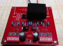
A lesser (but I think important) goal would be to protect the board from stray air currents to keep the system as stable as possible. This was accomplished by the use of some of my usual bleeding edge technology: a Tupperware dish covering the rig.
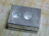
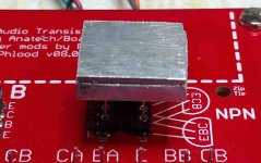
Going back to points 1 and 2 above, I built a simple aluminum cap that mounts onto and surrounds the two transistors and establishes thermal equilibrium between the pair. It’s deceptively simple – I used a very small block of aluminum measuring about ½ by 5/8” by ¼” thick. I drilled two holes through it using #10 bit which has a diameter of 0.193”. These two holes were spaced at 0.295” center to center, which is the distance between the two rows of the sockets. I cut a thin piece of aluminum to the same size and glued it to the first piece so that it serves as a cover. This is important because it provides flat bottoms to the holes and allows the tops of the transistors to sit flush against them. I super-glued only the corners so that I could put some thermal past between the two pieces.
To use this new thermal cap, I put a generous dab of thermal paste (damn, I hate working with that stuff) into each hole and gently pressed the it down onto the transistors. (BTW, I very lightly countersunk each hole to help it slide onto the transistors.) If I use the right amount of paste, I can look underneath and see a little bit squeeze out. This means I have paste filling most or all of the void spaces between the transistors and the cap, and thermal contact should be excellent.
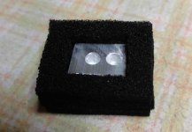
To insulate the thermal cap, I carved out a piece of foam and used this to cover the aluminum cap. This should help to stabilize the temperature of the whole thing.
BTW, some of you are probably thinking, “Wow, I could do this with copper (with about twice the thermal conductivity of aluminum) and it would work even better.” True enough, but mine was a quick and dirty prototype built as sort of a proof of concept. So far it seems to be working well. It was very simple to make and I encourage others to copy what I did and see if they get similar results. Copper may work better and I may give that a try. One thing I plan to try is to mount a small thermocouple in the thermal cap so that I can monitor temperature. This might allow us to investigate temperature effect and permit even closer matching.
Results? Using a pretty well matched pair of 2N5551’s, which come in at just under 1 mV, the rig stabilized within about a minute and sits like a rock. I use a Fluke 87V multimeter in high rez mode for the collector voltage and I can get pretty good accuracy. I will do some more work on this new piece of hardware and like I said earlier, if anyone thinks it might be a good approach, please build your own and report back with your results, along with any improvements you come up with.
One of the questions I’ve had all along is how much the transistors self-heat or warm up during testing. I calculated the heat generation at the recommended 3mA test current and came up with about 38 mW. (12.5v x 3.0mA). This is similar to an LED operating with a Vdrop of 2.0 volts and a current of 20 mA or about 40 mW. We don’t think of such an LED as getting particularly warm, but in their small TO-92 cases, the transistors will definitely warm up somewhat. I’ve tried using my Fluke IR gun but the transistors are just too small to get a meaningful temperature reading from. In any case, they will run above ambient and therefore be at least a little closer to their eventual operating temperature inside the amp.
It would be interesting to pursue calculations for heat dissipation for these transistors, because then we might be able to estimate tail currents that would help emulate the actual operating temperature of the transistors in the amp. However, I see two problems with this: first, we don’t generally know the internal amp temperature (and it probably doesn’t hold still for us); and second - and I think more importantly - each beta matcher test rig will be used a little differently in terms of thermal coupling and insulation (or fans, or whatever) , so we probably wouldn’t be able to establish a meaningful relationship between tail current and device temperature.
As I said earlier, I am now a fan of the thermal coupling method (pun intended). Based on this, I came to the conclusion that the two main goals of mounting the transistor pairs in the test rig are:
1) to mechanically and thermally couple them so that they remain at the same temperature; and
2) to shield them from stray air currents to minimize scatter and drift.
A lesser (but I think important) goal would be to protect the board from stray air currents to keep the system as stable as possible. This was accomplished by the use of some of my usual bleeding edge technology: a Tupperware dish covering the rig.
Going back to points 1 and 2 above, I built a simple aluminum cap that mounts onto and surrounds the two transistors and establishes thermal equilibrium between the pair. It’s deceptively simple – I used a very small block of aluminum measuring about ½ by 5/8” by ¼” thick. I drilled two holes through it using #10 bit which has a diameter of 0.193”. These two holes were spaced at 0.295” center to center, which is the distance between the two rows of the sockets. I cut a thin piece of aluminum to the same size and glued it to the first piece so that it serves as a cover. This is important because it provides flat bottoms to the holes and allows the tops of the transistors to sit flush against them. I super-glued only the corners so that I could put some thermal past between the two pieces.
To use this new thermal cap, I put a generous dab of thermal paste (damn, I hate working with that stuff) into each hole and gently pressed the it down onto the transistors. (BTW, I very lightly countersunk each hole to help it slide onto the transistors.) If I use the right amount of paste, I can look underneath and see a little bit squeeze out. This means I have paste filling most or all of the void spaces between the transistors and the cap, and thermal contact should be excellent.
To insulate the thermal cap, I carved out a piece of foam and used this to cover the aluminum cap. This should help to stabilize the temperature of the whole thing.
BTW, some of you are probably thinking, “Wow, I could do this with copper (with about twice the thermal conductivity of aluminum) and it would work even better.” True enough, but mine was a quick and dirty prototype built as sort of a proof of concept. So far it seems to be working well. It was very simple to make and I encourage others to copy what I did and see if they get similar results. Copper may work better and I may give that a try. One thing I plan to try is to mount a small thermocouple in the thermal cap so that I can monitor temperature. This might allow us to investigate temperature effect and permit even closer matching.
Results? Using a pretty well matched pair of 2N5551’s, which come in at just under 1 mV, the rig stabilized within about a minute and sits like a rock. I use a Fluke 87V multimeter in high rez mode for the collector voltage and I can get pretty good accuracy. I will do some more work on this new piece of hardware and like I said earlier, if anyone thinks it might be a good approach, please build your own and report back with your results, along with any improvements you come up with.
Attachments
Last edited:
Hey Anatech - even as a new member, I've already learned that for any post more than a couple of sentences long, I write it out in Word and then copy the whole thing to the forum once I'm done. I've accidentally hit some mystery button too many times and completely lost paragraphs of hard fought typing!
Hi Mike,
I have to say, you are determined. That's for sure!
Your "heat equalizer" will certainly do the job. I like the foam hat. However, I will agree that it is too messy and I would hate to deal with it as well. Being somewhat on the old and lazy side (having 100 little critters to test will do that to you), my jig has closer spacing and all I do is push the two parts together. Then I plop the foam "hat" over the pair and drop a box or whatever is close at hand over the entire setup. Once it has stabilised I take the readings and move on to the next pair. I often get sub mV pairs that are stable doing it this way that remain matched and stable once installed in the application. Using the jig that Coneniac sent for me to check is about as easy as the spacing is the same as mine. He dropped the outside pair of sockets as he isn't going to use adapters like I am. Adapters? Yes, I match SMT's as well. Now that, is a real PITA!!!
When I respond to posts, I just start writing without a preformed plan. You get it as it rolls out of my head as I think of the subject. I can't afford the time to write things out first. I'm usually busy at my bench and turn around now and again to clear my email. Too much to do.
Your idea about the thermal probe is a good one unique to you because of the way you equalise the temperature. It sounds like a very good idea.
Transistor heating. At these low power levels, there will only be a small amount of heating. Of course, now you can actually measure it with the temperature probe from ambient. Cool test. Your jig looks to be well built.
One thing I learned from building so many of these things, buy the expensive sockets or header strips! The inexpensive ones don't work very well.
-Chris
Hi Phloodpants,
That sounds promising. I'd be interested to hear your findings. You have done a lot of work on this already. Thank you.
Make a jig for testing SMT diff pairs, and maybe one for separate SMT transistors. I used a block of metal to hold them down and equalise the temperature. What a pain, balancing it. I think a hold down clamp might work better.
-Chris
I'm rescinding my previous findings regarding temperature tracking. I was NOT getting the two DUTs heated up evenly with method I was using. It's not enough to just thermal past and shrink-wrap.
I did another experiment, and Chris, your point about needing insulation around the transistors is confirmed and point well taken. Diego Mike thanks for your work on this too!
Thermal tracking of beta v temperature is—in fact—much better than my flawed experiment with the lamp showed. I had the transistors thermal-pasted and shrink-wrapped, but that doesn't stop one device from getting warmer than the other. The cases of the transistors are still exposed directly to air. As mentioned, air currents, radiated heat sources, and uneven heat-sinking from PCB traces can all cause imbalances.
So, I took a pair transistors that matched well via the fan method, and put them in this rather ludicrous-looking contraption. The transistors are thermal-pasted and shrink-wrapped along with a K-type thermocouple. I wrapped the DUTs in a few layers of cotton, and fitted a 10mm socket over the whole thing. The idea being that the thermal mass of the socket keeps the heat pretty even all around the DUTs, as the lamp heats the whole thing. The cotton insulation increases the thermal time constant, and provides insulation from physical contact with the socket. A smurf-hat of silicone tape keeps heat from escaping the socket. Now, when I apply the lamp, the thermal conduction of the socket should keep the heat pretty even all around.

Silly looking, but it seems to work! Look at this tracking.
That's going from room temperature, 22C to 60C in 30 minutes. Sorry, no graph of the temperature raise, but it was roughly linear.
They only differ over a 2% range, from room temp to 60C.
Here's the same pair, with the fan method, for 15 minutes.

The results are pretty close. This particular pair appears to be a match with the fan method, averaging just 0.25% positive, but at higher temperatures, they are off by 1.5% on average. The fan method does appear to keep the temperatures even, but the results are off because they are running so much cooler than in real life.
It also seems that there is a broad range of temperatures that are good to test at, but the fan method is too cool. Probably anything above 30C is fine.
It seems that having the insulation around the transistors is crucial. And I think having some kind of conductive metal thermal mass, a cap, all the way around is also a good thing, so that the transistors are surrounded by the same temperature from all directions. DiegoMike's contraption seems to do the trick as well, enforcing a common temperature through conduction.
It also suggests, that in order to keep these carefully matched devices actually matched in operation They should not just be thermal-pasted and shrink-wrapped, but they should at least have a layer of insulation, and perhaps a thermally conductive metal cap around the whole thing. I can easily envision scenarios in any amplifier, where one of a pair of matched transistors, happens to be sitting closer to a source of radiated heat like a heatsink. What my flawed experiment with the thermal-pasted-and-shrink-wrapped transistors actually showed, is that without insulation around the transistors, they will drift like crazy.
Perhaps we should be insulating and capping the transistors in our amps. I think a 3/8" copper pipe end-cap stuffed with some kind of insulation would be perfect.
I did another experiment, and Chris, your point about needing insulation around the transistors is confirmed and point well taken. Diego Mike thanks for your work on this too!
Thermal tracking of beta v temperature is—in fact—much better than my flawed experiment with the lamp showed. I had the transistors thermal-pasted and shrink-wrapped, but that doesn't stop one device from getting warmer than the other. The cases of the transistors are still exposed directly to air. As mentioned, air currents, radiated heat sources, and uneven heat-sinking from PCB traces can all cause imbalances.
So, I took a pair transistors that matched well via the fan method, and put them in this rather ludicrous-looking contraption. The transistors are thermal-pasted and shrink-wrapped along with a K-type thermocouple. I wrapped the DUTs in a few layers of cotton, and fitted a 10mm socket over the whole thing. The idea being that the thermal mass of the socket keeps the heat pretty even all around the DUTs, as the lamp heats the whole thing. The cotton insulation increases the thermal time constant, and provides insulation from physical contact with the socket. A smurf-hat of silicone tape keeps heat from escaping the socket. Now, when I apply the lamp, the thermal conduction of the socket should keep the heat pretty even all around.
Silly looking, but it seems to work! Look at this tracking.
That's going from room temperature, 22C to 60C in 30 minutes. Sorry, no graph of the temperature raise, but it was roughly linear.
They only differ over a 2% range, from room temp to 60C.
Here's the same pair, with the fan method, for 15 minutes.
The results are pretty close. This particular pair appears to be a match with the fan method, averaging just 0.25% positive, but at higher temperatures, they are off by 1.5% on average. The fan method does appear to keep the temperatures even, but the results are off because they are running so much cooler than in real life.
It also seems that there is a broad range of temperatures that are good to test at, but the fan method is too cool. Probably anything above 30C is fine.
It seems that having the insulation around the transistors is crucial. And I think having some kind of conductive metal thermal mass, a cap, all the way around is also a good thing, so that the transistors are surrounded by the same temperature from all directions. DiegoMike's contraption seems to do the trick as well, enforcing a common temperature through conduction.
It also suggests, that in order to keep these carefully matched devices actually matched in operation They should not just be thermal-pasted and shrink-wrapped, but they should at least have a layer of insulation, and perhaps a thermally conductive metal cap around the whole thing. I can easily envision scenarios in any amplifier, where one of a pair of matched transistors, happens to be sitting closer to a source of radiated heat like a heatsink. What my flawed experiment with the thermal-pasted-and-shrink-wrapped transistors actually showed, is that without insulation around the transistors, they will drift like crazy.
Perhaps we should be insulating and capping the transistors in our amps. I think a 3/8" copper pipe end-cap stuffed with some kind of insulation would be perfect.
- Home
- Design & Build
- Equipment & Tools
- Matching transistors & measuring the results