A step further to match mosfets.
Could you explain (just with few words) the advantage of the curcuit compared to the "single" circuit I used with 15V-10R-140mA?
Without knowledge, it looks to me that you have done quite a job to really reach a matched pair of fets!!
Mosfet testing craked
Full post on my tread
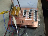
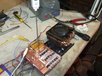
Maybe Transconductance write up tomorow for now see picture
Much more on my tread
Did not want to Hi Jack this one
Could you explain (just with few words) the advantage of the curcuit compared to the "single" circuit I used with 15V-10R-140mA?
Without knowledge, it looks to me that you have done quite a job to really reach a matched pair of fets!!
Full write up on my tread ....in a few words
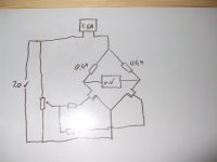
No difference in voltages and current pick the one you like
Why 2?
Because you subject both to the same enviroment EGG the left one used as compensating device right side the ones on test.
Changes in for example ambient temperature cancell out.
If both brances of the bridgewhere exactley the same you get zero reading at the meter.
This can not be as there may be a slight difference in the resistors so you get a small error (I got about 10mV) what you mesure is this errors if 2 mosfet gives you the same error they are the same
Keep swapping the one on the right and write down the difference
Once done you look for the ones that show the same difference
EGG 1)15mV 2)37mV 3)48mV 4)16mV 5)36mV 1 and 4 are preaty close matched and so are 2 and 5 3 and 1 not so good .
Al
Why 2?
Because you subject both to the same enviroment EGG the left one used as compensating device right side the ones on test.
Changes in for example ambient temperature cancell out.
If both brances of the bridgewhere exactley the same you get zero reading at the meter.
This can not be as there may be a slight difference in the resistors so you get a small error (I got about 10mV) what you mesure is this errors if 2 mosfet gives you the same error they are the same
Al
Hi Al,
You write things in a way that it's easy to understand.
I will stay with the single setup, and I understand the temperature balance and the more accurate reading by the "bridge" setup of yours.
rgds
Gudmund
 I've pulled several posts for rules violations (personal attacks). This will not be tolerated- further posts in this vein will cause suspension of posting privileges.
Hi Al,
from what I can see your circuit has a number of issues; as it is shown, the mosfets run at full conduction, which is lightyears away from real world working points. Remember, we want the parts to be matched at working conditions. So you need at least a CCS in the tail and even then the parts run in the linear region, which might give different results to matching in the saturation region, particularly if the fets are not from the same lot.
2nd, no temperature effects are compensated (except for the reference fet); imagine you start measuring in the morning (cool), during the whole day with a nice hot evening, the last measured fet sees different temperature conditions compared to the first measured one.
You can, however, use that circuit (with CCS) for differential pair matching.
Anyway, I think we're already pretty academic here")
from what I can see your circuit has a number of issues; as it is shown, the mosfets run at full conduction, which is lightyears away from real world working points. Remember, we want the parts to be matched at working conditions. So you need at least a CCS in the tail and even then the parts run in the linear region, which might give different results to matching in the saturation region, particularly if the fets are not from the same lot.
2nd, no temperature effects are compensated (except for the reference fet); imagine you start measuring in the morning (cool), during the whole day with a nice hot evening, the last measured fet sees different temperature conditions compared to the first measured one.
You can, however, use that circuit (with CCS) for differential pair matching.
Anyway, I think we're already pretty academic here
My question about matching is thus:
At idle, the internal resistance of a device, be it Mosfet or Bipolar, is essentially high. the device is only dissipating the Bias current through the device, which is typically very low. and at clip, the devices are essentially full on so there internal resistance is low. most of the power id being dissipated by the load and very little power is being dissipated by the device agan.
at 1/3rd power or half PSU voltage approximately. half the power is being dissipated by the load and half by the device. this is the worst operating condition for the device and the reason many reviewers will run an amp at 1/3rd power for a period of time to see how hot the amp/heatsinks get.
wouldn't it then make sense to match the devices where the power is being shared equally amongst devices under the worst operating condition the devices will see during operation?
Now maybe this makes more sense for a "Pro" PA system type amp for longevity is of more concern vs distortion as these amps are often abused.
and maybe it makes more sense to match at Bias current for a home amp where low distortion and equal current sharing at low power levels, AKA the first watt is of more importance?
These are questions I am asking? (yes i think too much)
Zc
Last edited:
Hi Zero Cool
I agree with you it does make sense to match as you say
Quote
wouldn't it then make sense to match the devices where the power is being shared equally amongst devices under the worst operating condition the devices will see during operation?
This will be once installed and running on the actuall amplifier with the connected speakers at working conditions.
And this is what I will do.
The idea of matching them before hand on a test rig is 1)to have repeatable results with a minimum set of conditions.
2) to eliminate a number of the mosfet to be tested at the operating conditions as this take quite a bit of time as EG you need to power down the amp remove the PCB
solder on the new mosfet power up and adjust at least the offset while the amplifier warms up and setles.
If yo have a look at the examples With this test I will nknow befor hand that mosfet 3 will not match the others and it will be then eliminated from the operating condition matching this may save 15 20 minutes and to have to solder and resolder one dudas
as there is a limited ammount of stress that the PCB will take.
HA tanks for the VCS pointer it is important and I will work on it
Sorry I can not agree with you about the temperature the reference and DUT are mounted very close to each other and the temperature is kept constant by the CPU fan,
As (and you probably know this beter than me) Vgs changes with temperature whith the rudimental test rig I am using I got this to setle in a couple of minutes or less.
The righ is kept at about 50C which should be enough to eliminate most of the enviromental difference by as you say measuring in the morning or air currents near the rig
Could you suggest a way to alowd for this differential testing at the linear region.
I was planning to change the 10 ohms with the specified 0R47 20V suply and use a regulated DC voltagge to the gates set so to have 1A 1.5A and 2A ids
would this be good enough for testing the transconductance by connecting one side of the volt meter to the suply return (note I say suply return as polarity changes between N and P channels)?
Attachments
...and maybe it makes more sense to match at Bias current for a home amp where low distortion and equal current sharing at low power levels, AKA the first watt is of more importance?
These are questions I am asking? (yes i think too much)
Zc
It seems to me that Zero Cool got a point by matching the mosfets at the bias current for a home amplifier.
By test equipment it is seen that the wattage power used in a 25 square meter living-room at normal listening level of 86-87dB stays a little under 1 watt RMS ( max 10-15watt at the spikes). Is the first 10 to 15 watt from a amplifier the more important power, even with ineffective speakers?
- Status
- This old topic is closed. If you want to reopen this topic, contact a moderator using the "Report Post" button.
- Home
- Amplifiers
- Pass Labs
- Matching Mosfets