with the sanding of the heatsink, i heard
"that everything above 500 grit is just polishing it and in extreem cases causes a loss in thermal conduction becuase the thermal interface goop that you use will cuase it to 'float' as there are no small pits for it to go into"
does this have any basis in reality?
"that everything above 500 grit is just polishing it and in extreem cases causes a loss in thermal conduction becuase the thermal interface goop that you use will cuase it to 'float' as there are no small pits for it to go into"
does this have any basis in reality?
I don't know about the sanding, but you can get hig performance siliocn pads, that I think will help with the heat much more than sanding.
However the high performance apds are rather expensive and you have to buy quite a lot. (around 1.0 US$/2500 pcs).
Maybe an ideer for a group-buy. ?
Thomas
However the high performance apds are rather expensive and you have to buy quite a lot. (around 1.0 US$/2500 pcs).
Maybe an ideer for a group-buy. ?
Thomas
Just to clarify a bit about my transformers.
It is a 1000VA toroid with 2x24vac secondaries.
And i also have 4 EI transformers with 250VA each. 24VAC single secondaries. The EI transformers are going to be used as monoblocks with 2 in each block. Each EI weighs.... 6kg!!
Nicks
It is a 1000VA toroid with 2x24vac secondaries.
And i also have 4 EI transformers with 250VA each. 24VAC single secondaries. The EI transformers are going to be used as monoblocks with 2 in each block. Each EI weighs.... 6kg!!
Nicks
autoexec said:with the sanding of the heatsink, i heard
"that everything above 500 grit is just polishing it and in extreem cases causes a loss in thermal conduction becuase the thermal interface goop that you use will cuase it to 'float' as there are no small pits for it to go into"
does this have any basis in reality?
From my experiments and other's reports when overclocking computer CPUs, I would say that they're wrong (or maybe using a thermal paste I haven't..). Hardcore overclockers would lap their heatsinks and the tops of the heatspreaders on their CPUs to a mirrored finish, then very carefully apply a very small amount of heatsink paste. This could give as much of a drop of 2-3 degrees.
The hardest part of doing this wass getting a perfectly flat surface to "lap" the heatsink/chip on. A lot of folks used a thick piece of glass, wrapped in sandpaper.
Nicks said:hi all again,
It seems to be hard finding the drv134 over here...
What about using SSM2142 from analog devices?
By the looks it should be the same thing (read same function).
Any comments?
It's a direct replacement. Go ahead.
Carlos
HI Nicks
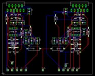
You should make your your tracks that carry large current much bigger. And maybe you should also make "on-board" regulators for your op-amps, then you only have to supply the +/- 35 V and you seems to have enough space for it.
You could also make the hole of one of your layers GND.
Have Fun
THomas
You should make your your tracks that carry large current much bigger. And maybe you should also make "on-board" regulators for your op-amps, then you only have to supply the +/- 35 V and you seems to have enough space for it.
You could also make the hole of one of your layers GND.
Have Fun
THomas
Hi Nicks
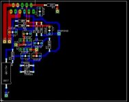
Looks better, but your output-tracks and some of your ground trakcs have to be bigger(the last depending on how you connect your speaker).
I would make a on-board regulator for your op-amp. And the OPA134 is not the best choice for low off-set as you need.
Have fun
Thomas
Looks better, but your output-tracks and some of your ground trakcs have to be bigger(the last depending on how you connect your speaker).
I would make a on-board regulator for your op-amp. And the OPA134 is not the best choice for low off-set as you need.
Have fun
Thomas
Tlmadsen, thank you for your support.
i was thinking of parallelling 4 chips on each side.
Then use the SSM2142 opamp to "split" the signal, giving 4 chips inverted signal and 4 chips noninverted.
Much like the BPA 200. but using 8 chips per channel.
so, i cant see the "need" for bigger ground tracks since the speaker never will be connected to it. I hope i am correct here.
which opamp do you recommend instead of the opa134?
Best regards
Nicks
Hi Nicks
You are right about the ground track if you connect your speaker (-) straigt to your PSU. However having low-resistance ground tracks/path is always good for your design.
I take it from your PCB that the opamp in question is the one used for the DC-servo ??
Using a OPA627 or AD8610 is totally wast of money and I will be VERY impressed if you can hear any difference.
Use something like LF412 or AD712 (dual, so you only need one with your two amps on each board))
Have a look at http://www.diyaudio.com/forums/showthread.php?s=&threadid=19157
2 x 4 LM3886 will give you Power, but make sure you get propper cooling, otherwise you can't take advantage of all your LM3886 (and running at +/- 42 V DC is OK).
Have fun
Thomas
- Status
- This old topic is closed. If you want to reopen this topic, contact a moderator using the "Report Post" button.
- Home
- Amplifiers
- Chip Amps
- Massive GC? Suggestions please