Hans, see the video about the problemNo idea where that may be in the circuit diagram.
To what bias current would that translate ?
Hans
I see what goes on, when in On mode the output swings to 32 Volt and the amp switches off, true ?
That would mean that the corresponding CG board is still O.K.
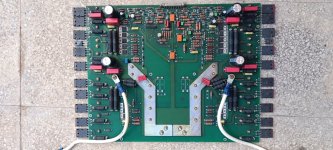
But the voltage on your power transistors should be +/-50Volt according to my documentation and not +/-62.5 Volt.
On your VG boards you should have +/-57.5 Volt.
Are both amps having this problem or just one?
Hans
That would mean that the corresponding CG board is still O.K.
But the voltage on your power transistors should be +/-50Volt according to my documentation and not +/-62.5 Volt.
On your VG boards you should have +/-57.5 Volt.
Are both amps having this problem or just one?
Hans
When you say one amp has a problem, do you mean one of the two amps the same physical housing or are you referring to the two separate amps for the right and the left channel.
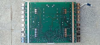
And yes, you can change the VG boards, that could confirm that the problem is in the VG board and not in the CG section.
Hans
And yes, you can change the VG boards, that could confirm that the problem is in the VG board and not in the CG section.
Hans
Thx.
I still don’t understand the large difference in the measured voltage versus the specified voltage of +/-50 Volt, but ML isn’t always that accurate.
But that is not the cause if your problem.
Let us know what you get after having switched the VG boards.
Did you also change caps on the VG board and if so, which numbers ?
Hans
That is a real problem.about the problem: i prove to regulate the trimmer offset(for regulate -1,2v), but never make change(in standby mode). i think for the shutdown reles, but do you think?
Which side is it, the non inverting or the inverting.
I'll tell you what to do when I know the correct side.
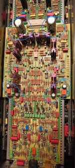
But in advance could you give me the voltages on Pin 2, 3, 4, 6 and 7 of the servo (U1 or U501 ?) in standby mode.
I see you changed both electrolytics for the servo supply, maybe something was not soldered good enough or a cap was mounted in the wrong direction.
Hans
P.S. I see you already told it was the positive side.
When I have your measurements on U1, I'll respond.
Last edited:
- Home
- Amplifiers
- Solid State
- Mark Levinson 33H calibration