Maybe, maybe not, it's always best to start off with very little, just enough to quell reflections around the driver and only add more if the pipe sounds too resonant, which I've found varies quite a bit from person to person. For sure I pay no attention to MJK's polyfil sims since virtually everyone that has stuffed based on a simmed smooth response of my designs has taken most of it back out and/or used something other than polyfil.
Anyway, a basic sim of JG's MLTL and your slightly smaller one with the same 0.5 lbs/ft^3 stuffing density:
GM
Anyway, a basic sim of JG's MLTL and your slightly smaller one with the same 0.5 lbs/ft^3 stuffing density:
GM
Attachments
![mark audio Alpair 10.2 MLTL [Jim Griffin].gif](/community/data/attachments/244/244083-47b1cc3e1ce1ffce775b22497f027eab.jpg)
![mark audio Alpair 10.2 6' PVC pipe MLTL [jij3].gif](/community/data/attachments/244/244086-5ccc281489f2a99fcf8a65ce4f051b5d.jpg)
You're welcome!
That would be 'Martin' and I assume you mean MLTL.........")
Right, all else equal, a smaller cross sectional area [CSA] dictates a 'shorter' pipe.
Unless he's changed his math from a 2D to 3D wave propagation in his more recent software, the WSs calculate a round wave; he apparently prefers to be able to input the dims for record keeping/whatever.
For simming a vertical bottom exit vent, just subtract the vent length from the total length, so whereas JG's vent is 44" down, yours would be 41.5", which as you can see in the sim makes a completely inaudible difference from a cab design POV; though in-room your vent will sound different to some extent depending on how much vent/floor gap there is and whether it's firing at a reflective or damped surface.
GM
That would be 'Martin' and I assume you mean MLTL.........
Right, all else equal, a smaller cross sectional area [CSA] dictates a 'shorter' pipe.
Unless he's changed his math from a 2D to 3D wave propagation in his more recent software, the WSs calculate a round wave; he apparently prefers to be able to input the dims for record keeping/whatever.
For simming a vertical bottom exit vent, just subtract the vent length from the total length, so whereas JG's vent is 44" down, yours would be 41.5", which as you can see in the sim makes a completely inaudible difference from a cab design POV; though in-room your vent will sound different to some extent depending on how much vent/floor gap there is and whether it's firing at a reflective or damped surface.
GM
![mark audio Alpair 10.2 6' PVC pipe MLTL [jij3] v2.gif](/community/data/attachments/244/244568-aa4620a851ebded888cf35e294e1b1a0.jpg)
Sorry about the typos....
Yes, the model shows the 5" port gives better low-end extension. If I have the port vertical out the bottom (the speaker will sit on 1.5" spikes over carpet) then to keep the 44" zport, the total length of the speaker will be 49". This looks quite good in the model, but then I agree this is "splitting hairs", since the differences seem very small from the original.
I'm now waiting on the fittings to come from ebay, and the driver from Dave (thanks, Dave). Mounting the driver will be the major trick. The pipes are currently cut longer (for 52") but I will listen and then trim and listen again. If I cut too short, my friend has a scrap heap of more 6" pipe.
Jack
This is a great project, Jack - will be really interesting to see your results.
I still can't get out of my head the idea of a pipe within a pipe with something like sand in between. Easy to do with pipes. Sand fill was how they used to build posh DIY speaker cabinets in the 50s!!
Andy
I still can't get out of my head the idea of a pipe within a pipe with something like sand in between. Easy to do with pipes. Sand fill was how they used to build posh DIY speaker cabinets in the 50s!!
Andy
This is a great project, Jack - will be really interesting to see your results.
I still can't get out of my head the idea of a pipe within a pipe with something like sand in between. Easy to do with pipes. Sand fill was how they used to build posh DIY speaker cabinets in the 50s!!
Andy
I am thinking about using sand or lead shot in the bottom of the pipe. The speaker is going to be unbalanced and tending to fall forward once the driver is mounted, and this could be another easy way to shorten the transmission line while tuning. The 6" schedule-40 pipe I'm using has 3/8" thick walls and is pretty inert. The 6" schedule-80 pipe has 1/2" thick walls but is expensive. The sewer pipe you found on-line is probably thinner walled.
Actually, another cylindrical transmission line could be a hollowed-out tree trunk. Probably have trouble keeping the cat off it though...
Jack
I'm now waiting on the fittings to come from ebay, and the driver from Dave (thanks, Dave).
Despite it being the Grey Cup today (go Lions) i should get the last of the spots on today.
dave
Despite it being the Grey Cup today (go Lions)
+1
I am thinking about using sand or lead shot in the bottom of the pipe. The speaker is going to be unbalanced and tending to fall forward once the driver is mounted, and this could be another easy way to shorten the transmission line while tuning. The 6" schedule-40 pipe I'm using has 3/8" thick walls and is pretty inert. The 6" schedule-80 pipe has 1/2" thick walls but is expensive. The sewer pipe you found on-line is probably thinner walled.
Actually, another cylindrical transmission line could be a hollowed-out tree trunk. Probably have trouble keeping the cat off it though...
Jack
Ah - that's much thicker pipe than I thought - nice!!
A couple of hollowed out upended alligators would look cool, since you're in Florida. Curl the tails around to make useful stands.
andy
PVC pipe MLTL proof of concept
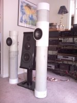
In the course of this project I have learned more than I ever wanted about PVP pipe specs. It all started with a local source of "Schedule 40" 6" PVC pipe. The first Tees I bought off of ebay turned out to be for drain pipe, and did not fit. I was however able to jury-rig one up with a scrap piece of Sch 40 pipe to mount one of my Alpair 10.2 EN drivers (from Dave) for break-in. It is on the left of the photo. Shorter than optimal, but actually sounding very good!
I then bought some real Sch 40 Tees (much more expensive...) and came up with the speaker on the right. It is close to Jim Griffin's dimensions (L=46.1", Zd=16", Zp=46", So=Sl=182 cm2). I am planning to cut and inch off the top to give L=45.1, Zd=15, Zp=45. (I have found that Martin King's sheets don't like L=Zp.) There are 25 lbs of lead shot (inside old socks) wrapped completely around a 5" vertical port (1" radius) firing out the bottom. It stands on 1 3/8" spikes. It is still breaking-in, so I can't comment on sound yet.
This is truly an easy project for those of us wood-working challenged. The only real trick is getting the driver mounted securely and as close as possible to the vertical column. The drain pipe Tee was much easier to work with, and may be practically identical in performance. The Sch 40 Tee presented an oblong opening after I cut off the horizontal arm. I used 1" long rings cut square (with a band saw) off the ends of the 6" PVC pipe, fitted and glued to the inside of the Tee opening, and screwed the drivers to their cut ends. I cut open each ring to the proper length (circumference) and placed them in a 300F oven for about 10 min. They come out as soft 1" wide strips of plastic, maleable to any shape. I molded each to the opening let it cool and glued (welded) it inside the opening. When dry it was ready for pilot holes and mounting screws. PVC requires more torque when turning the screws in the pilot holes than does wood, and I stripped one screw head. Fortunately Dave sent me a couple of relacements, thanks Dave.
OK they are cosmetically challenged. I am soliciting advice on beautification. I am considering fitting a whole body sock for each speaker made of grill cloth fabric.
Jack
Attachments
Another possibility might be wrapping the top and bottom sections with carpet and allowing the t and end caps to remain as is. Really looking forward to hearing your comments on sound quality once the drivers break in. I'm guessing the rounded shape will help them disappear and image like gangbusters!
(I have found that Martin King's sheets don't like L=Zp.)
I am soliciting advice on beautification.
???
Slick looking!
Whatever works best overall with the room decor/WAF unless you want them to stand out like a 'sore thumb', in which case I'm partial to brite white, accent shaded with Dayglo orange to create a Creamsicle 'look'
. GM
One added benefit of using automotive carpet is the backing might be helpful in dampening any structure borne resonances. Might be subtle but then again sometimes all those little things add up. Another thought too is you might want to try some kind of a "footing" under the speaker, such as a wood, marble, granite, that will allow the port opening to fire into the room more without getting muffled by the carpet and its underlying padding. This would be easy enough to try both ways and see what you prefer. Again "kudos" for a nice design!
Thanks for the advice. Once the speaker is broken in, I will try setting it on wood as opposed to carpet.
Interestingly, the short jury-rigged prototype using the sewer Tee is sounding very, very good, now that its driver is fairly broken in.
I think I am going to be very happy with these speakers. Their only limitation is likely to be that sometimes I like to listen at high volume, and these drivers do have limited SPL. So, my next thought is to add a second driver to each speaker. It would be almost trivial to stick one on the top firing up. Given the Tinker-Toy ease in taking the speaker apart, changing tube lengths is easy, but changing the cross-sectional area is not.
I have Martin King's MathCad sheets, and there is a sheet for a MLTL bipole with 2 drivers mounted on the front and back, but nothing for one driver at the end of the TL and the other mounted at 90 degrees further down the line. Does anyone know how to use one of these sheets to model such a speaker? Any thoughts on whether it would be worth the trouble?
Thanks, Jack
I enjoy the high volumes at times too. I mean lets be honest a concert grand piano at real life volumes is a joy that not many speakers can pull off without some nasty distortion creeping in. I'd love to know the results you get with adding a second driver facing the ceiling. My guess is if you do it right you will add immensely to the scale and realism as long as most of the up firing signal can bounce around for 10 mil sec or more before arriving at your listening position along with the main forward firing drivers. Please post pics of whatever you come up with.
I have Martin King's MathCad sheets, and there is a sheet for a MLTL bipole with 2 drivers mounted on the front and back, but nothing for one driver at the end of the TL and the other mounted at 90 degrees further down the line. Does anyone know how to use one of these sheets to model such a speaker? Any thoughts on whether it would be worth the trouble?
You have some options:
1/ model an ML-TL with 2 end loaded drivers (or with 1 and then double the cross-section). Similar to Castle microTower.
2/ move the driver on the back to the side
3/ model an 2 driver ML-TL, then top mount one driver, and then place the 2nd such that the average position is at the specified Zd. The further the drivers apart the more the actual build will deviate from the sim. As well front driver may end up kinda low.
dave
many thanks, Dave
For option 1, using the model with one speaker and doubled Sd, if I wire the speakers in parallel, should not the Re be halved? Should the Vad be doubled as well as Sd? If I do this, the sim looks pretty good, with the double speaker mounted at the top or at 15" down from the top. Do you think I could actually mount another driver to the top of the existing column as is and expect good results?
For options 2 and 3,are you referring to the TL_ML_Bipole_Corner_7_03_09 file?
Jack
Last edited:
I went over to MJK's Yahoo Group, and with Martin's guidance, I have modeled the speaker using a double-sized driver positioned halfway between the forward-firing driver and the top of the TL. Yes, there is more ripple because of the higher position of the driver on the column. The bass also begins to fall off 10 hz higher because of the relatively small cross-section. The only way to prevent this is by doubling the cross-section of the TL and the port.
I may try it anyway with the two drivers I have, since anything I do with the PVC is easily reversible, and I do use a subwoofer for the lowest bass.
Jack
I may try it anyway with the two drivers I have, since anything I do with the PVC is easily reversible, and I do use a subwoofer for the lowest bass.
Jack
- Status
- This old topic is closed. If you want to reopen this topic, contact a moderator using the "Report Post" button.
- Home
- Loudspeakers
- Full Range
- Mark Audio Alpair 10 MLTL Design