rowemeister said:Just looked at the op amp circuit, the gain of 2.7x is from the 27K and 10K resistors then
Brent
You've just won a microwave oven
Ray.
6h5c said:
You've just won a microwave oven
Ray.
WOW thanks Ray.
Although I was hopeing for the speed boat.
rowemeister said:
Having not spent any time working with the HDAM and just bypassing it. What would it sound like with no opamp and DAC straight to HDAM?
Will the gain and filtering be all wrong
Brent
Luke said:Hi Ray,
would your discrete output stage work on a cd6000? Think the main difference between the two is that the cd6000 has two dacs not one. If it should be ok to use, should I proceed it with the filter you have designed, or will it not be appropriate for cd6000?
Wher do you get the inductors from, and should they be high precision, or matched components?
Cheers arthur
Hi.
This is what happens in the CD6000 OSE
Andy
Luke said:Hi Ray,
would your discrete output stage work on a cd6000? Think the main difference between the two is that the cd6000 has two dacs not one. If it should be ok to use, should I proceed it with the filter you have designed, or will it not be appropriate for cd6000?
Wher do you get the inductors from, and should they be high precision, or matched components?
Cheers arthur
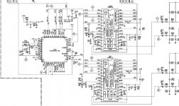
Hi Arthur,
The CD6000 is a bit more complicated because of the two DAC's. Marantz uses one for each channel, and that leaves us with four outputs for each channel that have to be summed, instead of two. First, they sum the RO/RON and LO/LON outputs with two opamps, and then they use the HDAM circuit to sum the two opamp outputs. Some filtering is done in both stages. As Andy states, in the OSE and KI they use HDAM circuits instead of the opamps. Both circuits have two inputs and one output, so they can be regarded the same.
To replace all this with passive filtering and discrete stages you would need eight passive filters, one for each output, four differential stages to sum these outputs, and two more to sum the outputs of these four. Since the DAC's are the same as in the CD63/67 I think my filter will work fine, but perhaps you will have a problem fitting it all on the board somehow
Since the HDAM circuit is already a discrete stage, maybe you can replace the opamp-part only.
Or you can take the "Microsoft approach" and use only one output of the DAC, like Thorsten Loesch does in this article. I tried this filter and tubestage too and it works very good. The gain is a bit low though.
The next solution could be: get rid of the TC160G11 chip that generates the data for the separate DAC's and use a single DAC for both channels, just like in the CD63/67. That would be one piece of silicon nastyness less in the signal path. But this would be HIGHLY experimental (don't you love it ????).
BTW, the inductors are nasty indeed, I get them from Farnell. I buy a few more than I need and pick out pairs that match best.
Regards,
Ray.
6h5c said:What DAC is that? PCM1716? That has part of the analog filter integrated on the chip (yuk). Hence the simple LPF. With SM5872 I think there will be some noise residue with such a simple filter.
Regards,
Ray.
Yep its a PCM1716.
mmmm poop
rowemeister said:
Yep its a PCM1716.
mmmm poop
player still useful as transport.
spdif from decoder or better still use the i2s out, if either available
external dac
allan
awpagan said:
................player still useful as transport...............
Or buy a CD63 / 67 and modify it !!!!!
IMO using a cd-p as a transport is a NO-NO !
Either buy a dedicated transport and a good dac
or
Buy a cd-p with a good front end and modify the dac etc.
The spdif out on most cd-ps is a low cost compromise.
Better still, build your own no-compromise cd-p from scratch !
poynton said:
Or buy a CD63 / 67 and modify it !!!!!
IMO using a cd-p as a transport is a NO-NO !
Either buy a dedicated transport and a good dac
or
Buy a cd-p with a good front end and modify the dac etc.
The spdif out on most cd-ps is a low cost compromise.
Better still, build your own no-compromise cd-p from scratch !
Thats why i got the CD67
but if you have a spare cdprayer sitting around
cheaper to mod and learn
ps learn? the electronics and also what to listen for.
yes cdm-pro2, i2s out, dac? undecided on which dac still.
That's why i also said i2s out
Function control for the transport?
easy to adapt an old cdplayer control panel.
allan
Ray,
thanks for your imformative post. I think maybe I skip the new output stage on the cd6000 and get round to doing this on my cd67, I like easy
Although the solution Thorsten gives seems ok, why cant the gain be upped?
I actually think the cd67 has way more potential than 6000, but its taking me along time to get through this project. Will post some pics when Im done.
seeya arthur
Luke said:Ray,
thanks for your imformative post. I think maybe I skip the new output stage on the cd6000 and get round to doing this on my cd67, I like easy
Although the solution Thorsten gives seems ok, why cant the gain be upped?
I actually think the cd67 has way more potential than 6000, but its taking me along time to get through this project. Will post some pics when Im done.
seeya arthur
Hi Arthur,
Indeed the 67 is much easier. The 6000 has lots of extra silicon on board and a more complicated clock distribution. I think it will sound better in the end too.
Thorsten's circuit works and sounds fine, but the gain of the tube buffer is max. 1x. That's because the lower tube acts as a kathode follower. For a gain >1 you need a different circuit.
Regards,
Ray.
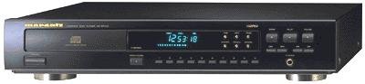
OOPS, did it again.....
I couldn't resist, I bought a CD57 for 25 euro's.....
Attachments
6h5c said:
Ray.
OOPS, did it again.....
I couldn't resist, I bought a CD57 for 25 euro's.....
for this one a fet output(buffer) stage?
allan
Hi All,
A slight aside...
I've not had the chance to tinker recently, but I was listening the other night, and for quite a while not listened to any CD-Rs.
To my amazement, I noticed that my CD63 now plays all CD-Rs without fault!!!
Beforehand, it would be okay, but it might stop on a track change, especially if you skipped ahead a few tracks.
Now its fine.
Really not sure which mod made the difference, maybe it was a collection. I can't help thinking it was the added weight on the clamp, but that's just a hunch.
Ray,
I dug out Horowitz to reinforce my theory on diff amps. Still can't quite remember the specific benefits of removing the emitter resistors, bar that they are supposedly negligible, but if simulations suggest a difference, then its worth it.
BTW what do you simulate with? I tend to avoid simulation purely because I often design on paper (I sit in front a PC for a living), but there are obvious benefits.
Cheers,
Phil
6h5c said:I think I will try that anyway
Ray.
How much balance is useful on the input pair?
i have some 2sk368's and 2sj109'ssitting waiting for something
allan
philpoole said:Ray,
I dug out Horowitz to reinforce my theory on diff amps. Still can't quite remember the specific benefits of removing the emitter resistors, bar that they are supposedly negligible, but if simulations suggest a difference, then its worth it.
BTW what do you simulate with? I tend to avoid simulation purely because I often design on paper (I sit in front a PC for a living), but there are obvious benefits.
Cheers,
Phil
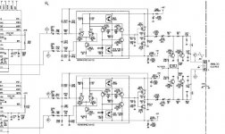
Hi Phil,
Emitter resistors bring thermal stability. As temperature rises, Ube will be lower, so Ic will rise. The drop across Re increases because of the higher Ic, so that will compensate for the lower Ube.
They also provide local feedback, so they can be used to set the amplification of the stage.
I found a good site here.
For simulations I use Micro-Cap 7.0. I do not navigate blindly on it, but it is a very handy tool.
Regards,
ray.
Attachments
awpagan said:How much balance is useful on the input pair?
i have some 2sk368's and 2sj109'ssitting waiting for something
allan
I wanted the input stage to be as balanced as possible, so for the input stage I matched the resistors and the BC550's Hfe with my transistor tester, but I don't have a tool for FET's. And besides, I only have the four that originally came out of the HDAM
.It cancels the noise that's common in both DAC outputs, so a good balance doesn't hurt.
Ray.
Hi dont want to go off topic but I bought some 22000uF Silmics which are very rare for my KI amp.
They have arrived and i'm starting to think they won't fit. LOL
They have arrived and i'm starting to think they won't fit. LOL
An externally hosted image should be here but it was not working when we last tested it.
- Home
- Source & Line
- Digital Source
- Marantz CD63 & CD67 mods list