Glenn2 said:I'm a bit out of my depth here I think...
Out of your bit depth you mean

I got my CD63 back from the vets on Friday and had a listen at Lee's house, which was nice (nice setup you have Lee, including the awesome dog). The Super Reg on the DAC's digital power supply input has made a lovely improvement, the treble in particular is just superb. Detail levels are also first rate, easily wiping the floor with my budget SACD player (but he's not modded yet).
I've now been able to have a first listen of this mod at home with my newly upgraded preamp (simple discrete buffer, and now with über sockets and shorter wiring using shaft extenders), powered from S Powers.
For the first time I can truly say it's the music that you notice first, rather than treble, mids and bass when trying (or not trying) to analyse the system's performance. Having said that, there's no bass from my speakers so I'll have to experiment with different speaker designs. This became obvious after hearing great, deep bass from Lee's little Jamo Concert 8 speakers.
Simon
Glenn2 said:Ray - this question is probably up your straat, having built dacs!
Is it:
BCK = 48fs = 48 * 44.1kHz = 2.1168MHz
LRCK = fs = 44.1kHz
(System clock = 384*fs = 384 * 44100 = 16.9344MHz)
So am I right in thinking that for 2x16-bit words, the bit clock only theoretically needs to be 32fs but they chose 48fs back then, and now 64fs seems to be the norm?
Presumably it would have to got through some kind of SRC to be usable with a newer DAC chips. I'm a bit out of my depth here I think...
You don't need an ASRC (but it will work great, might as well upsample to 24/96
") , the sample frequency of the audio-signal doesn't have to be altered, only the FORMAT in which it is transmitted. Most modern DAC's can accept 48*Fs format AFAIK; worst case you need some logic between the decoder and DAC.
, the sample frequency of the audio-signal doesn't have to be altered, only the FORMAT in which it is transmitted. Most modern DAC's can accept 48*Fs format AFAIK; worst case you need some logic between the decoder and DAC.I'd already assumed the output of the decoder is I2S, but the BCK frequency is indeed 2.1168MHz, which corresponds to the 'Sony' or EIAJ format. I2S uses 32 clocks framelength (= 64*Fs), and EIAJ uses 24 (= 48*Fs).
Looking at the datasheets, both the SAA7345 and 7372 can output I2S with 48*Fs, which would differ from the 'official' I2S specification.
I'm a bit confused too, which is it? Anyone?
Ray
Hi Ray,
This baffled me too, from the Wolfson WM8741.
(Read text in picture first).
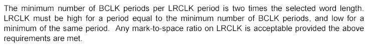
The first line makes sense because you need two words - one for each channel - per LRCLK period.
So that would mean (LRCLK = fs) that 2x16 bit words = 32 BCLK periods mimimum = 32fs.
But then LRCLK must be high for the minimum number of BCLK periods and then low for the minimum number which totals 64 BCLK periods to one LRCLK.
Russ White (he of Twisted Pear) told me that the modern DACs need 64fs bit clocks.
(I did notice that the only I2S mode supported in hardware mode for this DAC is 24-bit words anyway, so it would have to be used in software mode to access I2S 16-bit, but that's another can of worms.)
I'm also rather interested in his ESS Sabre DAC boards. Those who've tried this chip say it's so jitter resistant that it doesn't discriminate between good and bad transports even via S/PDIF. The S/PDIF receiver, ASRC, digital filter and current-out DAC are all on the same chip, allowing some new tricks. Interesting stuff.
This baffled me too, from the Wolfson WM8741.
(Read text in picture first).
The first line makes sense because you need two words - one for each channel - per LRCLK period.
So that would mean (LRCLK = fs) that 2x16 bit words = 32 BCLK periods mimimum = 32fs.
But then LRCLK must be high for the minimum number of BCLK periods and then low for the minimum number which totals 64 BCLK periods to one LRCLK.
Russ White (he of Twisted Pear) told me that the modern DACs need 64fs bit clocks.
(I did notice that the only I2S mode supported in hardware mode for this DAC is 24-bit words anyway, so it would have to be used in software mode to access I2S 16-bit, but that's another can of worms.)
I'm also rather interested in his ESS Sabre DAC boards. Those who've tried this chip say it's so jitter resistant that it doesn't discriminate between good and bad transports even via S/PDIF. The S/PDIF receiver, ASRC, digital filter and current-out DAC are all on the same chip, allowing some new tricks. Interesting stuff.
Attachments
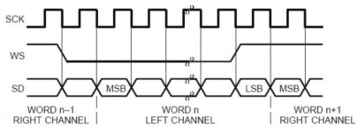
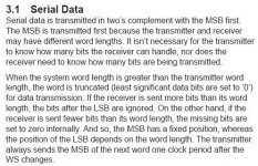
Don't mix up the length of the SIGNAL, which is 16 bits, and the length of the FORMAT it is transported in. The word lenght of I2S is 32 BCK cycles, so for two words per sample (L and R) you get 64*Fs. The signal length can be 16 or 24 bit, most converters automatically detect this. It's MSB first, so if the rest are zero's, that's not a problem.
Why the SAA decoders output 24 bit word length, I don't know. But if the DAC just waits for LRCK (WS) to change, it won't be a problem.
Why would a DAC 'need' 64*Fs BCK? The SM5872 doesn't
Not to be confused with the SYSTEM clock...
Ray
Why the SAA decoders output 24 bit word length, I don't know. But if the DAC just waits for LRCK (WS) to change, it won't be a problem.
Why would a DAC 'need' 64*Fs BCK? The SM5872 doesn't
Not to be confused with the SYSTEM clock...
Ray
Attachments
Discrete Output Stage
Hi Ray,
I've now constructed and installed your Discrete Output Stage into my SA-8260.
It's great!!!!!!!
It's only been in for a few days, so limited listening. But you hear the improvement in EVERYTHING from the first notes of the first disc. The music sounds clearer, cleaner, and is a lot more dynamic than "before". And I had a fairly well modified output stage "before". I'd say that this project is highly recommended!!
I did make a few substitutions to your design. In the LPF section I used Texas Component TX2352 resistors and Rel RTE polystyrene caps. I also substituted a BG 47uf/6.3v NX cap for the BG 100uf/16v N cap, as I already had the smaller caps and have used them in the modified stock board.
One thing I didn't do is use Tent or Dexa regulators, because they are expensive, but I find the music so good now, that I may reconsider the expensive regulators, and just go for broke.
I can't do a diy board, so I used www.expresspcb.com as they have a 3 board offer for not too much.
Anyway Ray, hats off to you for a brilliant design here. It's truly Einsteinian, in the mode of "as simple as necessary but no simpler".
Re: Discrete Output Stage
Your comments are highly encouraging.
I will soon report the benefits of a similar mod.
Ricardo
stvnharr said:Hi Ray,
It's only been in for a few days, so limited listening. But you hear the improvement in EVERYTHING from the first notes of the first disc. The music sounds clearer, cleaner, and is a lot more dynamic than "before". And I had a fairly well modified output stage "before". I'd say that this project is highly recommended!!
Anyway Ray, hats off to you for a brilliant design here. It's truly Einsteinian, in the mode of "as simple as necessary but no simpler".
Your comments are highly encouraging.
I will soon report the benefits of a similar mod.
Ricardo
Re: Re: Re: Discrete output
Hi Brent
I can hear the hiss if I turn the volume up without any CD playing.
Should a 470uF BG STD after each spower remedy this small issue ?
Regards
Ricardo
rowemeister said:
Yes of course different resistors and caps alter the sound but I find the large improvement comes from the regulators and psu feeding it, and second the caps (eg 220uf BG std) change the sound alot. Both these alter the sound much more.
I have of course tested quite abit with the discrete pcbs and they have a large bandwidth compared to opamps, If you feed noise into them you get noise out (altered sound).
The SPower regulators I use are very fast response and if I use no or a very little cap (10nF) across the feedback resistor the discrete pcb will emit hiss (like a tape deck), opamps remove this higher freq.
Audiocom superregs and Qpower by comparison have a slower response time and don't create hiss on this pcb, they have a larger cap on the feedback which slugs down the response of the reg.
Hi Brent
I can hear the hiss if I turn the volume up without any CD playing.
Should a 470uF BG STD after each spower remedy this small issue ?
Regards
Ricardo
Re: Discrete Output Stage
Hi Steve,
That's a decent player for a D.O.S.! Great to hear that it works so well. But, fair is fair, some credit must go to Remco Stoutjesdijk for setting up the initial circuit. I just shaped it into what it is now, and designed the passive filter. I'm not Einstein, i'm a lazy guy , but thanks for your great compliments!
I haven't actually tried it with standard regulators like 78/79xx, but went for the shunts straight away. But pls. do report! I'm very curious if the difference is big, like Brent reports. I will also add this kind of stuff to my website.
Regards,
Ray
stvnharr said:Hi Ray,
I've now constructed and installed your Discrete Output Stage into my SA-8260.
It's great!!!!!!!
...
Hi Steve,
That's a decent player for a D.O.S.! Great to hear that it works so well. But, fair is fair, some credit must go to Remco Stoutjesdijk for setting up the initial circuit. I just shaped it into what it is now, and designed the passive filter. I'm not Einstein, i'm a lazy guy
, but thanks for your great compliments!I haven't actually tried it with standard regulators like 78/79xx, but went for the shunts straight away. But pls. do report! I'm very curious if the difference is big, like Brent reports. I will also add this kind of stuff to my website.
Regards,
Ray
Re: Re: Discrete Output Stage
Hi Ray,
I'll be sure to report when I install new regulators, about a month or so. Any thoughts on my use of the smaller BG cap @ C11? Am I compromising anything in your design by using it?
Steve
6h5c said:
Hi Steve,
That's a decent player for a D.O.S.! Great to hear that it works so well. But, fair is fair, some credit must go to Remco Stoutjesdijk for setting up the initial circuit. I just shaped it into what it is now, and designed the passive filter. I'm not Einstein, i'm a lazy guy
I haven't actually tried it with standard regulators like 78/79xx, but went for the shunts straight away. But pls. do report! I'm very curious if the difference is big, like Brent reports. I will also add this kind of stuff to my website.
Regards,
Ray
Hi Ray,
I'll be sure to report when I install new regulators, about a month or so. Any thoughts on my use of the smaller BG cap @ C11? Am I compromising anything in your design by using it?
Steve
Re: Re: Discrete Output Stage
Hi Ricardo,
I've been following your progress here.
Just curious, how did you do your board?
Steve
RCruz said:
Your comments are highly encouraging.
I will soon report the benefits of a similar mod.
Ricardo
Hi Ricardo,
I've been following your progress here.
Just curious, how did you do your board?
Steve
Re: Re: Re: Discrete Output Stage
Hi Steve. I am etching it for him, as I am also doing a new one for myself, so I can use Kiwame resistors (although I'm dubious about how much better they may be over the melf smt's I currently use).
I have been playing about with the layout, trying to accommodate a large Mundorf film cap, but this is proving problematic to say the least.
Regards, Lee.
edit: are those smaller Nx caps only 6.3v? If so, you may well be running them over-voltage as the dc offset in my discrete stage is around 7.1v.
stvnharr said:
Hi Ricardo,
I've been following your progress here.
Just curious, how did you do your board?
Steve
Hi Steve. I am etching it for him, as I am also doing a new one for myself, so I can use Kiwame resistors (although I'm dubious about how much better they may be over the melf smt's I currently use).
I have been playing about with the layout, trying to accommodate a large Mundorf film cap, but this is proving problematic to say the least.
Regards, Lee.
edit: are those smaller Nx caps only 6.3v? If so, you may well be running them over-voltage as the dc offset in my discrete stage is around 7.1v.
Re: Re: Re: Re: Discrete Output Stage
Great. A 47u cap is fine, the low cut-off frequency is very low, so no problem. But....
... that is a problem! The cap should be at least 16V working voltage!
Regards,
Ray
stvnharr said:Hi Ray,
I'll be sure to report when I install new regulators, about a month or so. Any thoughts on my use of the smaller BG cap @ C11? Am I compromising anything in your design by using it?
Steve
Great. A 47u cap is fine, the low cut-off frequency is very low, so no problem. But....
Thomo said:edit: are those smaller Nx caps only 6.3v? If so, you may well be running them over-voltage as the dc offset in my discrete stage is around 7.1v.
... that is a problem! The cap should be at least 16V working voltage!
Regards,
Ray
Re: Re: Re: Re: Re: Discrete Output Stage
Yes the small BG NX is 6.3v, which means I'm likely maxing it out. Easy to measure offset. I've got some larger caps, though not N or NX, here and can swap something in if necessary.
6h5c said:
Great. A 47u cap is fine, the low cut-off frequency is very low, so no problem. But....
... that is a problem! The cap should be at least 16V working voltage!
Regards,
Ray
Yes the small BG NX is 6.3v, which means I'm likely maxing it out. Easy to measure offset. I've got some larger caps, though not N or NX, here and can swap something in if necessary.
6h5c said:That would be better, because I also don't know what the circuit does exactly at power-up. I could very well be that the cap is submitted to +/-12V for a short period of time...
Ray
I just measured the offset at 3.01v at idle. When playing, the offset was 0.6 or so and seemed to vary. Pretty hard to measure at power up, but there could very well be a big surge as you suggest.
It'd be really nice to have a film cap here, but they are a bit too large. I do have a big 1uf/600V Mundorf film cap on the amp input, no preamp.
Steve
Re: Re: Re: Re: Discrete Output Stage
Lee is providing that part for me.
How is the work going ?
Regards
Ricardo
Hi Stevestvnharr said:
Hi Ricardo,
I've been following your progress here.
Just curious, how did you do your board?
Lee is providing that part for me.
Hi LeeThomo said:
I have been playing about with the layout, trying to accommodate a large Mundorf film cap, but this is proving problematic to say the least.
How is the work going ?
Regards
Ricardo
6h5c said:That's not right, did you measure before the cap? It should be around +6V, measured to GND, because there's around 18V across the 1k8 resistor and that's tied to -12V on one side. And it should stay like that when playing, because it's a class-A circuit.
Ray
Ray,
Measured this time before the cap and it's +7.0V. Previous measurement was after the cap. Stout cap!
Guess I'd better be finding something in my big box of caps to put in there. I know I have a few Rubycon ZA's and Zl's of 220uf and large enough voltage.
Steve
That's better. Looks like you killed the cap  --->
--->  --->
---> 
You only need a few uF for a -3dB corner freq. that's <<10Hz (with a 47k load), but if you want to keep the group-delay low at the low-end, use 10uF minimum. You should roughly double these values for a 22k load.
Ray
---> ---> You only need a few uF for a -3dB corner freq. that's <<10Hz (with a 47k load), but if you want to keep the group-delay low at the low-end, use 10uF minimum. You should roughly double these values for a 22k load.
Ray
- Home
- Source & Line
- Digital Source
- Marantz CD63 & CD67 mods list