Here is another mod I just implemented. I built a Super Regulator:
http://www.sinigersky.com/images/JSR02+5V_pic2.jpg
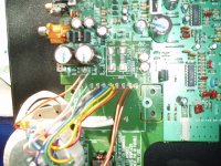
and fitted it into the player to power the analog pins of the DAC:
http://www.sinigersky.com/images/Marntz-DAC-PS-fit1.jpg
The voltage for the input of the super regulator comes from near the pins of Q811. I have drilled a small hole in the pad just between CD12 & CD13 and cut away the trace that brings the power to that pad.
The average noise gain is about 1-1,5 dB!!!
I have tried the following variations:
1) One wire from reg out to DAC --> increased intermodulation distortion + noise (I thought the ground currents should remain as they were)
2) GND of reg output connected to junction U208 --> better intermodulation distortion!
3) power also digital part of DAC with the same reg (cut U200 and feed a second wire from reg to it) --> slightly increased noise
4) use a 10 mH inductance instead of U200 (digital part of DAC powered by the original 7805) and connect reg ground to U221 --> best performance, similar to 2)
...And the listening experience: this is the next major improvement after installing the new clock. New details revealed that I never heard before! Really recommended!!!!
Any other ideas about the grounding?
Note: the mounting accessories for the regulator PCB are not connected with the GND on the PCB!
http://www.sinigersky.com/images/JSR02+5V_pic2.jpg
and fitted it into the player to power the analog pins of the DAC:
http://www.sinigersky.com/images/Marntz-DAC-PS-fit1.jpg
The voltage for the input of the super regulator comes from near the pins of Q811. I have drilled a small hole in the pad just between CD12 & CD13 and cut away the trace that brings the power to that pad.
The average noise gain is about 1-1,5 dB!!!
I have tried the following variations:
1) One wire from reg out to DAC --> increased intermodulation distortion + noise (I thought the ground currents should remain as they were)
2) GND of reg output connected to junction U208 --> better intermodulation distortion!
3) power also digital part of DAC with the same reg (cut U200 and feed a second wire from reg to it) --> slightly increased noise
4) use a 10 mH inductance instead of U200 (digital part of DAC powered by the original 7805) and connect reg ground to U221 --> best performance, similar to 2)
...And the listening experience: this is the next major improvement after installing the new clock. New details revealed that I never heard before! Really recommended!!!!
Any other ideas about the grounding?
Note: the mounting accessories for the regulator PCB are not connected with the GND on the PCB!
rowemeister said:Here are two more pics of my discrete pcb with 7812, 7912, 2x cerefine and a 4.7uF wima fitted for testing.
Brent
Hey Brent,
Your PCB looks very nice! But what is the reason you used SMD's for the caps and resistors? Is the cost factor?
This way it's not possible to use silver-mica's or polystyrenes in the filter. Ceramics are not a good choice for audio, or did you manage to get some nice SMD film caps?
Regards,
Ray
Hi Ray
Yes it's a combination of cost and space trying to make a nice neat package with a good performance.
We built a few prototypes with smd and normal + using different caps and resistors.
We found the very short track traces on the smd pcb had better treble control and seemed to lose nothing to the larger version in mid range or bass.
When testing the different caps and resistors we found the polystyrene caps gave a little more warmth to the sound over ceramic caps, but the silver mica were nearly identical.
We tried different ceramic caps and found differences here too, the really cheap ones added a brittle edge to the treble and make highs in vocals a little harsh.
At the moment we are using ceramic COG types as we found these to be quite neutral, on the pcb only 4 are in the filter and non in the amp section.
The biggest difference in audio came from the selection of the smoothers as you would expect and of course the regulators, low noise ones make a huge difference.
Comparing the pcb to the different opamps is night and day in audio terms - very natural and open sounding, nothing added nothing taken away (but you know this already).
Brent
Hi Brent yep looking good.
On the subject of cost any ball park figures yet?
While we're at it I've been looking through your latest mods list and the circuit diags for the transformers.
Everyone says reg nearest the load, so I'm fine with them all except DAC analogue.
So.........
1) Where do you put your 2x BG 16v 1000uF BG's ?
2) You said Thomo's 16v 470's would be fine. Does it make much difference in any of the locations you've uses the 1000 uF's?
I know I keep banging on about regs but I want to get it right.
Thanks
Jim
Hi Jim
The 2X 1000uF caps are mounted onto the Invisus pcb, no room around the dac as they are big caps.
Those 16V 470uF caps are superb and fit nicely next to the dac (2x 470uF for dac ana). The 2000uF makes very little difference over the 940uF to be honest, a little better for bass and smoothness.
My 1000uF are approx 3cm away from the dac on the reg as the Invisus is a bit bulky. I may swap it for a SPower and get it right on the dac.
Still testing the discrete pcb with different cd players before release but it looks like a pcb with 78 79 regs and cerefines (no output cap) will be in the £75 inc vat region (PAIR). I will also be able to fit SPower regs and BG at extra cost (of course).
MOD LIST
Brent
Are you going to supply the pcb's for us to butcher ourselves? LOL
I have my original KI which I managed to bu**er up and asked you about months ago.
Couldn't figure it out then so got a cheap SE off eBay and been modding that.
Going to either
1) Put the SE PCB in the KI with KI tranny until I get all the separate trannies sorted out like yours.
2) Try and get the KI working or failing that
3) Send the KI pcb to some bloke in Doncaster who might be able to perform miracles!!
It's probably something dead simple but it was beyond me when I first started.
One thing puzzles me though. The voltages from the trannies are all the same except at U307. The SE reads 16.5v and the KI 33.6v. The KI transformer has two yellow leads going to U307. Is this reght for a KI do you think?
JIm


Yes the discrete pcb will go on sale to get butchered 
A bloke in donny hey wonder who that is LOL
All the voltages should be the same! that 33.6 is double the 16.5V.
Did you take any pics of where the original wires went on the KI?
Take a piccy of the wiring you have done and post it on here so we can check it out.
The Yellow leads should go to U309
Brent
A bloke in donny hey
wonder who that is LOLAll the voltages should be the same! that 33.6 is double the 16.5V.
Did you take any pics of where the original wires went on the KI?
Take a piccy of the wiring you have done and post it on here so we can check it out.
The Yellow leads should go to U309
Brent
Hi Brent
Yeh dunno who the bloke in Donny is but he doesn't seem to get a lot of work done tinkering with CDP's all day!! LOL
Been trying to insert an image but think I need hosting?? to do that.
Have emailed instead.
I haven't moved the TX yet.
All I've done is reattach the orange lead at C801 when I thought it had come away.
Thought the voltage was wrong when I checked it against the SE.
Rgds
Jim
jimh0612 said:been trying to insert an image but think I need hosting?? to do that.
Jim,
You need to click on "Browse..." in the "Attach file" section below the message area. Select your file, but it must be <100Kb otherwise DIY-A won't have it! Resize and apply JPEG compression as much as necessary.
Simon
Solder blob under U309 to star shaped ground under U274.
Dunno if I've blown something inside the TX.
I did have a mishap when the tranny moved while the CDP was powered up and the mounting bracket may have shorted something.
I had attached an earth to the IEC socket which also slipped and shorted to the live at JH02.
And me a builder - I work with electrics all the time. (PI**OCK!!)
(Sheepish) Jim
jimh0612 said:Grey wire at C802.
C801 and C802 are unpopulated.
Not very good at following service manual schematics I'm afraid.
Jim
The Orange and gray wires are not shown in the service manual as they are connected internally of the tx on the 63 and SE
Brent
jimh0612 said:Solder blob under U309 to star shaped ground under U274.
Dunno if I've blown something inside the TX.
I did have a mishap when the tranny moved while the CDP was powered up and the mounting bracket may have shorted something.
I had attached an earth to the IEC socket which also slipped and shorted to the live at JH02.
And me a builder - I work with electrics all the time. (PI**OCK!!)
(Sheepish) Jim
LOL
Where is U274 i've gone blind
Also here is a drawing I have done of the KI TXs outputs on good old ms paint
KI TX OUTPUTS
Brent
- Home
- Source & Line
- Digital Source
- Marantz CD63 & CD67 mods list