martin clark said:Ditto the 'carefully' bit - most scopes have their 0v input bolted to mains earth...
Anyway, looking at the mains makes for depression - see bottom pic here:
http://www.acoustica.org.uk/other/mains_noise.html
- and the fixes usually proposed don't work:
http://www.acoustica.org.uk/other/filter.html
Best to remove the earth from the plug of the scope
Brent
SimontY said:
Too right! I'm too scared to put a DVM probe in a live socket after the last time (it got a bit melted and blasted out). Don't ask me what I did!
LOL
You had it switched to current, a dead short (well a shunt resistor) across mains....BANG!!!!
Brent
Apologies for my contributing to a poor signal to noise ratio on this thread, but this post is serious, I promise! ")
Ok, many thanks for the tips Andrew. Btw I think I misunderstood Brent's original suggestions slightly. He didn't want the "safety earth" connected to the "secondary" circuits.
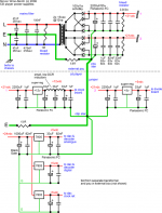
I have taken in all advice and ammended my schematic accordingly. I have decouple safety earth using 6.8R. I have also removed the think multiple earths from PSU to reg boards. All earths travel to a star and from one star to the other. Anyway, "pictures speak louder than..." (know the film?)
Is this ok now chaps?
Simon
Ok, many thanks for the tips Andrew. Btw I think I misunderstood Brent's original suggestions slightly. He didn't want the "safety earth" connected to the "secondary" circuits.
I have taken in all advice and ammended my schematic accordingly. I have decouple safety earth using 6.8R. I have also removed the think multiple earths from PSU to reg boards. All earths travel to a star and from one star to the other. Anyway, "pictures speak louder than..." (know the film?)
Is this ok now chaps?
Simon
Attachments
Depending on the scope, that's a bad idea. Much better to use suitable way for isolating scope from the mains - suitable isolating transformer, 2KV rated caps in sense side etc. There's info on this on the Tektronix website (their 'ABCs of using an Oscilloscope' document and others - well worth reading anyway).
I actually use a wideband transformer in a plastic box plugged into a disposable laptop (my ancient G3 powerbook) - running on its battery.
I actually use a wideband transformer in a plastic box plugged into a disposable laptop (my ancient G3 powerbook) - running on its battery.
SimontY said:Apologies for my contributing to a poor signal to noise ratio on this thread, but this post is serious, I promise!
Ok, many thanks for the tips Andrew. Btw I think I misunderstood Brent's original suggestions slightly. He didn't want the "safety earth" connected to the "secondary" circuits.
I have taken in all advice and ammended my schematic accordingly. I have decouple safety earth using 6.8R. I have also removed the think multiple earths from PSU to reg boards. All earths travel to a star and from one star to the other. Anyway, "pictures speak louder than..." (know the film?)
Is this ok now chaps?
Simon
Looks ok. I would leave the res in the cdp off first and test
Brent
A few pics of my player atm
The IEC socket, new mains cable, and filter.
The main set of new caps on the pcb. Rubycon ZL's used in the most important areas. Re-used some silmics, and cerafines from my dead players.
The working op-amp area, with the audiocom 12V regs (installed yesterday).
An overview of the pcb, with the clock (bottom right) connected to a dedicated PSU (bottom left).
Finally, my 5V reg pcb for the decoder digital + analogue rails (x2 super-regs) and a 7805 for the Xtal input.
The IEC socket, new mains cable, and filter.
An externally hosted image should be here but it was not working when we last tested it.
The main set of new caps on the pcb. Rubycon ZL's used in the most important areas. Re-used some silmics, and cerafines from my dead players.
An externally hosted image should be here but it was not working when we last tested it.
The working op-amp area, with the audiocom 12V regs (installed yesterday).
An externally hosted image should be here but it was not working when we last tested it.
An overview of the pcb, with the clock (bottom right) connected to a dedicated PSU (bottom left).
An externally hosted image should be here but it was not working when we last tested it.
Finally, my 5V reg pcb for the decoder digital + analogue rails (x2 super-regs) and a 7805 for the Xtal input.
An externally hosted image should be here but it was not working when we last tested it.
Hi Simon,
Allmost there with post4464.
The grounding after each regulator shows a string of low resistances from the reg 0v to the caps.
I suggest the grounds for ALL the caps following each regulator be starred to the respective regulator 0v terminal.
Then the ground wire goes from each regulator star to the cdp star (audio ground).
I disagree on the E to CDP star, keep the 6r8 and add 10nF or 22nF 250V cap in parallel.
How low is lowDCR in the little inductors? 50T of 0.6mm enamelled copper?
Please give us an update on the sound effect of each series of changes, particularly the ones that don't work.
cheers lads, it does look a whole lot different in a picture than it does in real life. Im loving the sound now, and yes simon, i will leave it alone for a bit.
Only thing to put in this next week is the 5V reg board. Then im done until at least xmas
AS for music, im bidding on 'The battle for los angeles' on ebay atm. Good old bit of 'Rage' to see what this baby can do. Will also be buying some 'OK GO', 'Wolfmother', and 'Nerina Pallot' to have a good listen to !
 , and i need to do more work.
Just found a couple of varistors in my spares pile. Farnell #318607 - any use for trying out on the incoming mains supply to the player?
Cheers
Greg
Cheers
Greg
AndrewT said:Hi Simon,
Allmost there with post4464.
Excellent!
The grounding after each regulator shows a string of low resistances from the reg 0v to the caps....
All these parts are wired point to point by their own leads. I don't think I can realistically improve on this.
I disagree on the E to CDP star, keep the 6r8 and add 10nF or 22nF 250V cap in parallel.
I'm not sure who you're disagreeing with. I can add such a cap. Although for the first changes I will leave this safety earth connection in (and make sure there is nothing else connected directly ie. psu, power amp, pre amp, x-over.) I do have some hum that needs fixing.
How low is lowDCR in the little inductors? 50T of 0.6mm enamelled copper?
My meter reads about 2 ohms. I'd say fewer than 50 turns, probably more like 20. I measured the inductance but don't have it handy.
Please give us an update on the sound effect of each series of changes, particularly the ones that don't work.
You can be sure I will!
1 - I will start with CDP connected directly and the psu connected via the network you proposed. I will assess noise and hum levels.
2 - I will disconnect completely the psu star from house earth and assess.
Hopefully progress will have been made by this point and not to forget I will be disconnecting those other earth runs from psu to cdp and installing a large earth jumper between stars. I take it you agree with this part?
Cheers,
Simon
- Home
- Source & Line
- Digital Source
- Marantz CD63 & CD67 mods list