SimontY said:Thanks, it's quite broadband and steady, sounds random, like white noise, all frequencies. Audible at listening seat at medium-high levels on v. quiet passages or paused/stopped.
Si
edit: also the image is skewed to the left (otherwise sounds stunning)
Hi Simon,
Maybe a connection to ground in the filter is bad, like some cap that is not connected. Due to bad filtering the HF noise residue becomes greater, and the amplitude of the signal too, because the slope of the filter is less steep. Hence the skew to the left.
Regards,
Ray.
Re: Re: Re: Cd65
Those lasers used to play through any scratch
Brent
6h5c said:
Hey, great links Allan, thanks. I'm going to look for the CD782 manual too.
Nostalgia....
If I look at how this player is built, for those years it is awesome! I also like the swingarm transport a lot.
One of the players has been used very little. It looks like new, and the laser is propably good for years to come
Ray.
Those lasers used to play through any scratch
Brent
6h5c said:Hi Simon,
Maybe a connection to ground in the filter is bad, like some cap that is not connected. Due to bad filtering the HF noise residue becomes greater, and the amplitude of the signal too, because the slope of the filter is less steep. Hence the skew to the left.
Regards,
Ray.
Ooh, very interesting
Sounds like that could be the problem Re: Re: Re: Re: Cd65
brent
which lasers? cdm4's
allan
rowemeister said:
Those lasers used to play through any scratch
Brent
brent
which lasers? cdm4's
allan
Re: Re: Re: Re: Re: Cd65
Yep, they were a bugger to set up though!
Brent
awpagan said:
brent
which lasers? cdm4's
allan
Yep, they were a bugger to set up though!
Brent
Group Buy - Back on ?
Hi.
Has everyone seen that the terrible twins, Elso and Jocko, have been banned from the forum?
http://www.diyaudio.com/forums/showthread.php?s=&threadid=79338
So, is the clock board back on, Ray ? LOL
Andy
Hi.
Has everyone seen that the terrible twins, Elso and Jocko, have been banned from the forum?
http://www.diyaudio.com/forums/showthread.php?s=&threadid=79338
So, is the clock board back on, Ray ?
LOLAndy
Re: Group Buy - Back on ?
How do you know it was those two?
Brent
poynton said:Hi.
Has everyone seen that the terrible twins, Elso and Jocko, have been banned from the forum?
http://www.diyaudio.com/forums/showthread.php?s=&threadid=79338
So, is the clock board back on, Ray ?
Andy
How do you know it was those two?
Brent
Re: Re: Group Buy - Back on ?
easy - look at their previous posts on the forum.
Banned !
Andy
rowemeister said:
How do you know it was those two?
Brent
easy - look at their previous posts on the forum.
Banned !
Andy
Re: Re: Re: Group Buy - Back on ?
Beat you to it lol
Brent
poynton said:
easy - look at their previous posts on the forum.
Banned !
Andy
Beat you to it lol
Brent
Re: Group Buy - Back on ?
Hi Andy,
I noticed it a few weeks ago. It took Elso unusually long to respond on that clock PCB thing, so I looked him up and saw that he was banned, just like some other individuals, who are enjoying themselves very much on the other DIY forum....
Yeah, how about a thousand pieces to start with .
.
[serious]
I'd be happy to donate the clock PCB data if anyone wants to start a group-thing with it.
But maybe the Flea PCB is a better option. It's already been made and I think the performance
is at least equal, if not better.
[/serious]
Regards,
Ray.
poynton said:Hi.
Has everyone seen that the terrible twins, Elso and Jocko, have been banned from the forum?
Hi Andy,
I noticed it a few weeks ago. It took Elso unusually long to respond on that clock PCB thing, so I looked him up and saw that he was banned, just like some other individuals, who are enjoying themselves very much on the other DIY forum...
.
So, is the clock board back on, Ray ?
Andy
Yeah, how about a thousand pieces to start with
.[serious]
I'd be happy to donate the clock PCB data if anyone wants to start a group-thing with it
.But maybe the Flea PCB is a better option. It's already been made and I think the performance
is at least equal, if not better.
[/serious]
Regards,
Ray.
gy21 said:for R613 ... 616 (27R resistors in opamp section) I could get the replacement values of 1,5mH 22R at my local electronics shop, are these ok values?
Hi gy21,
These would be o.k. But if you can get 1mH or 470uH with a lower DC resistance that would be even better.
Regards,
Ray.
CD63 Logic Problem??
Hi Guys and greetings from down under!
I've been following this thread from the very beginning and have been meaning to make a post, but I never got around to it. Thanks to all the members who contributed to this thread... I've managed to learn heaps and follow most of the mods posted here!
I have a CD63 Special Edition, and I bought it second hand for NZ$ 250 two years ago, just for modding. Unfortunately in New Zealand, the exotic mod stuff (Audiocom Super regs, etc.) that you have access to in the UK is very expensive when the price is converted, so I've had to make do with more "mainstream" RS Components stuff.
I had modded the major components in my player before this thread was begun by Ray (6h5c), but I'm glad that he made that first post, because after seeing it, I opened up the player again... after about 1 year of happy listening. With more of the "advanced" mods posted here, I have to admit that the machine sounds better than ever now (well, it was sounding better than ever until last week... more on that shortly)
My main mods are what have been posted in PDF format by Ray and Brent. I did elect to keep the HDAM modules after bypassing them and listening .... Although the sound seemed cleaner initially without the HDAM, I thought it lost a bit of musicality when driving my Musical Fidelity X-Can V2s converted for duty as a preamp .
My mods on the CD63 are as follows:
1. Replaced most digital/analogue electrolytics with Rubicon ZL 1000uF and bypassed these with Wima film caps from the underside of the board
2. Replaced all diodes for IR Hexfreds
3. Replaced all resistors with RS Components "low noise" 1% tolerance stuff
4. Replaced ALL metal jumpers on the main board and transport daughter board with pure copper (had some spare Audioquest solid core speaker cable lying around that was the right diameter for the jumpers)
5. Swapped opamps with LM6172s (with power supply bypass caps on the opamps)
6. Replaced the resistors in the power supply lines with Murata EMI suppression filters and paralleled them on the underside with chokes
7. Shielded all the ICs and opamps with copper foil and grounded them
8. Modified the analogue filter (changed the component values) according to that published by Pedja Rogic (http://users.verat.net/~pedjarogic/audio/cd_mods/cd_mods.htm)
9. Did the clock mods and PSU bypassing according to Acoustica.org
When Ray and Brent posted their mods, I became increasingly curious about supplying the digital circuitry with clean power, so I opened up the 63 again after an year or so and did the following:
10. I’ve got one 10V pre-reg feeding 2 5V regs feeding the clock and the digital supplies (DAC + Decoder analog and digital).
11. 1 ~25V pre-reg feeding another positive 15V reg for the opamps + HDAM positive (couldn’t get the negative to work yet)
12. Used RG174 coax to bring the HF signal direct to the main board via SMB connectors
13. Used the remaining RG174 coax to replace the clock digital lines as highlighted in Brent’s PDF
14. Inserted a schaffner AC line filter in the back so an IEC power cord can be used
15. IEC Earth to star ground as per Brent’s PDFs
Needless to say… with all these mods, the machine was sounding pretty awesome. All credit and many thanks to those who’ve pushed the boundaries of modding this awesome CD player. I’ve benefited so much from everyone’s contribution, but I don’t feel that I can add anything unique other than to say for those of you who’ve done it all….replacing ALL the metal jumpers with some pure copper solid core wire WILL improve the sound without any side effects. If you look at these metal jumpers on the main board, they carry everything from ground signals to power to digital and clock signals. I’ve replaced these metal jumpers in all my other equipment as well, and the end result is that there’s more “THERE” there… so to speak.
I was really enjoying the incremental mods I was making on the CD63, but, last week, I ran into a problem that I just can’t seem to solve… and I’m hoping that some of you in this forum could help:
I ordered a custom spec’d crystal (16.9344 Mhz) from Rakon in NZ to replace the stock CD63 crystal (since an LC audio clock is just too expensive for me at the moment). The specs were as follows (I took an educated guess when doing the specs as I’ve no idea what the circuit conditions were… I was hoping it would just work):
Fundamental Frequency: 16.9344 MHz
Operating Temp: 0-50 C
Calibration Tolerance: +/-5 PPM
Frequency Stability: +/-3 PPM
Circuit Conditions: 18pF – parallel resonance mode
Ageing per year: +/- 0.5 PPM
Frequency Perturbation: 0.1 PPM
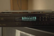
I anxiously replaced the stock crystal with the custom spec’d one AND against my better judgement, I did another mod and replaced the DAC clock out to Decoder clock in line with RG174 cable (U193 to C521). When I powered up the CD63, initially the disc started spinning backwards really fast… and diagnosis mode said error 10 (radial error). So I swapped the original Marantz crystal back, and now when I power up, nothing happens, except that the display lights up with ALL the digits/characters, yet the front buttons don’t work. Powered down and power up again…. No display…… wait for 5 minutes and power up again, and the display again displays these weird characters, and I can’t even get into service mode. I have checked that there’s 5V into the DAC, Decoder, CPU, Servo, and the flexi-cable from the transport to the mainboard seems fine.
Do any of you have any suggestions as to what this may be? I’ve put everything back to what it was when it was working properly except the U193-C521 clock line… but I’ve checked the continuity of it and all’s fine.
Any help in diagnosing this would be most appreciated… I’m totally gutted!
Thanks guys for a great thread… and I hope to be able to join to the conversation in when I get this CD63 singing again. If anyone wants to know more about my mods, please feel free to ask.
Champi
Hi Guys and greetings from down under!
I've been following this thread from the very beginning and have been meaning to make a post, but I never got around to it.
Thanks to all the members who contributed to this thread... I've managed to learn heaps and follow most of the mods posted here! I have a CD63 Special Edition, and I bought it second hand for NZ$ 250 two years ago, just for modding. Unfortunately in New Zealand, the exotic mod stuff (Audiocom Super regs, etc.) that you have access to in the UK is very expensive when the price is converted, so I've had to make do with more "mainstream" RS Components stuff.
I had modded the major components in my player before this thread was begun by Ray (6h5c), but I'm glad that he made that first post, because after seeing it, I opened up the player again... after about 1 year of happy listening. With more of the "advanced" mods posted here, I have to admit that the machine sounds better than ever now (well, it was sounding better than ever until last week... more on that shortly)
My main mods are what have been posted in PDF format by Ray and Brent. I did elect to keep the HDAM modules after bypassing them and listening .... Although the sound seemed cleaner initially without the HDAM, I thought it lost a bit of musicality when driving my Musical Fidelity X-Can V2s converted for duty as a preamp .
My mods on the CD63 are as follows:
1. Replaced most digital/analogue electrolytics with Rubicon ZL 1000uF and bypassed these with Wima film caps from the underside of the board
2. Replaced all diodes for IR Hexfreds
3. Replaced all resistors with RS Components "low noise" 1% tolerance stuff
4. Replaced ALL metal jumpers on the main board and transport daughter board with pure copper (had some spare Audioquest solid core speaker cable lying around that was the right diameter for the jumpers)
5. Swapped opamps with LM6172s (with power supply bypass caps on the opamps)
6. Replaced the resistors in the power supply lines with Murata EMI suppression filters and paralleled them on the underside with chokes
7. Shielded all the ICs and opamps with copper foil and grounded them
8. Modified the analogue filter (changed the component values) according to that published by Pedja Rogic (http://users.verat.net/~pedjarogic/audio/cd_mods/cd_mods.htm)
9. Did the clock mods and PSU bypassing according to Acoustica.org
When Ray and Brent posted their mods, I became increasingly curious about supplying the digital circuitry with clean power, so I opened up the 63 again after an year or so and did the following:
10. I’ve got one 10V pre-reg feeding 2 5V regs feeding the clock and the digital supplies (DAC + Decoder analog and digital).
11. 1 ~25V pre-reg feeding another positive 15V reg for the opamps + HDAM positive (couldn’t get the negative to work yet)
12. Used RG174 coax to bring the HF signal direct to the main board via SMB connectors
13. Used the remaining RG174 coax to replace the clock digital lines as highlighted in Brent’s PDF
14. Inserted a schaffner AC line filter in the back so an IEC power cord can be used
15. IEC Earth to star ground as per Brent’s PDFs
Needless to say… with all these mods, the machine was sounding pretty awesome. All credit and many thanks to those who’ve pushed the boundaries of modding this awesome CD player. I’ve benefited so much from everyone’s contribution, but I don’t feel that I can add anything unique other than to say for those of you who’ve done it all….replacing ALL the metal jumpers with some pure copper solid core wire WILL improve the sound without any side effects. If you look at these metal jumpers on the main board, they carry everything from ground signals to power to digital and clock signals. I’ve replaced these metal jumpers in all my other equipment as well, and the end result is that there’s more “THERE” there… so to speak.
I was really enjoying the incremental mods I was making on the CD63, but, last week, I ran into a problem that I just can’t seem to solve… and I’m hoping that some of you in this forum could help:
I ordered a custom spec’d crystal (16.9344 Mhz) from Rakon in NZ to replace the stock CD63 crystal (since an LC audio clock is just too expensive for me at the moment). The specs were as follows (I took an educated guess when doing the specs as I’ve no idea what the circuit conditions were… I was hoping it would just work):
Fundamental Frequency: 16.9344 MHz
Operating Temp: 0-50 C
Calibration Tolerance: +/-5 PPM
Frequency Stability: +/-3 PPM
Circuit Conditions: 18pF – parallel resonance mode
Ageing per year: +/- 0.5 PPM
Frequency Perturbation: 0.1 PPM
I anxiously replaced the stock crystal with the custom spec’d one AND against my better judgement, I did another mod and replaced the DAC clock out to Decoder clock in line with RG174 cable (U193 to C521). When I powered up the CD63, initially the disc started spinning backwards really fast… and diagnosis mode said error 10 (radial error).
So I swapped the original Marantz crystal back, and now when I power up, nothing happens, except that the display lights up with ALL the digits/characters, yet the front buttons don’t work. Powered down and power up again…. No display…… wait for 5 minutes and power up again, and the display again displays these weird characters, and I can’t even get into service mode. I have checked that there’s 5V into the DAC, Decoder, CPU, Servo, and the flexi-cable from the transport to the mainboard seems fine. Do any of you have any suggestions as to what this may be? I’ve put everything back to what it was when it was working properly except the U193-C521 clock line… but I’ve checked the continuity of it and all’s fine.
Any help in diagnosing this would be most appreciated… I’m totally gutted!
Thanks guys for a great thread… and I hope to be able to join to the conversation in when I get this CD63 singing again. If anyone wants to know more about my mods, please feel free to ask.
Champi
Attachments
Hi Champi,
Thanks for your kind words. I'm glad you enjoy this thread and got to modding your player again.
However, the latest event is less fortunate of course....
When you swapped the clock line for coax, did you take out C521 and couple the pins directly and put the coax in instead? The reason I ask is because when I was looking at it in my CD67 I noticed a DC component of about half the supply voltage on the clock-input of the SAA. That's the main reason Marantz put a 470R resistor in series with this line. In a CD63 I modded a while ago there was a 390R resistor in place of U193 and a series input cap.
Bottom line is: could it be this DC component has destroyed something? I noticed a fair amount of DC current flowing when I tried to lower the 470R resistor.
Regards,
Ray.
Attachments
Re: Re: Re: Cd65
ray
did you find the cd65 or cd782 manual?
allan
6h5c said:
the CD782 manual
Ray.
ray
did you find the cd65 or cd782 manual?
allan
Re: CD63 Logic Problem??
Hi
Glad you like the mods.
Your problem is not caused by the crystal.
To me its micro processor related. Check the 5V to the processor.
You may have a crack or dry joint in the pcb and this missing V rail or gnd is causing problems.
Brent
pantera6 said:Hi Guys and greetings from down under!
I've been following this thread from the very beginning and have been meaning to make a post, but I never got around to it.
I have a CD63 Special Edition, and I bought it second hand for NZ$ 250 two years ago, just for modding. Unfortunately in New Zealand, the exotic mod stuff (Audiocom Super regs, etc.) that you have access to in the UK is very expensive when the price is converted, so I've had to make do with more "mainstream" RS Components stuff.
I had modded the major components in my player before this thread was begun by Ray (6h5c), but I'm glad that he made that first post, because after seeing it, I opened up the player again... after about 1 year of happy listening. With more of the "advanced" mods posted here, I have to admit that the machine sounds better than ever now (well, it was sounding better than ever until last week... more on that shortly)
My main mods are what have been posted in PDF format by Ray and Brent. I did elect to keep the HDAM modules after bypassing them and listening .... Although the sound seemed cleaner initially without the HDAM, I thought it lost a bit of musicality when driving my Musical Fidelity X-Can V2s converted for duty as a preamp .
My mods on the CD63 are as follows:
1. Replaced most digital/analogue electrolytics with Rubicon ZL 1000uF and bypassed these with Wima film caps from the underside of the board
2. Replaced all diodes for IR Hexfreds
3. Replaced all resistors with RS Components "low noise" 1% tolerance stuff
4. Replaced ALL metal jumpers on the main board and transport daughter board with pure copper (had some spare Audioquest solid core speaker cable lying around that was the right diameter for the jumpers)
5. Swapped opamps with LM6172s (with power supply bypass caps on the opamps)
6. Replaced the resistors in the power supply lines with Murata EMI suppression filters and paralleled them on the underside with chokes
7. Shielded all the ICs and opamps with copper foil and grounded them
8. Modified the analogue filter (changed the component values) according to that published by Pedja Rogic (http://users.verat.net/~pedjarogic/audio/cd_mods/cd_mods.htm)
9. Did the clock mods and PSU bypassing according to Acoustica.org
When Ray and Brent posted their mods, I became increasingly curious about supplying the digital circuitry with clean power, so I opened up the 63 again after an year or so and did the following:
10. I’ve got one 10V pre-reg feeding 2 5V regs feeding the clock and the digital supplies (DAC + Decoder analog and digital).
11. 1 ~25V pre-reg feeding another positive 15V reg for the opamps + HDAM positive (couldn’t get the negative to work yet)
12. Used RG174 coax to bring the HF signal direct to the main board via SMB connectors
13. Used the remaining RG174 coax to replace the clock digital lines as highlighted in Brent’s PDF
14. Inserted a schaffner AC line filter in the back so an IEC power cord can be used
15. IEC Earth to star ground as per Brent’s PDFs
Needless to say… with all these mods, the machine was sounding pretty awesome. All credit and many thanks to those who’ve pushed the boundaries of modding this awesome CD player. I’ve benefited so much from everyone’s contribution, but I don’t feel that I can add anything unique other than to say for those of you who’ve done it all….replacing ALL the metal jumpers with some pure copper solid core wire WILL improve the sound without any side effects. If you look at these metal jumpers on the main board, they carry everything from ground signals to power to digital and clock signals. I’ve replaced these metal jumpers in all my other equipment as well, and the end result is that there’s more “THERE” there… so to speak.
I was really enjoying the incremental mods I was making on the CD63, but, last week, I ran into a problem that I just can’t seem to solve… and I’m hoping that some of you in this forum could help:
I ordered a custom spec’d crystal (16.9344 Mhz) from Rakon in NZ to replace the stock CD63 crystal (since an LC audio clock is just too expensive for me at the moment). The specs were as follows (I took an educated guess when doing the specs as I’ve no idea what the circuit conditions were… I was hoping it would just work):
Fundamental Frequency: 16.9344 MHz
Operating Temp: 0-50 C
Calibration Tolerance: +/-5 PPM
Frequency Stability: +/-3 PPM
Circuit Conditions: 18pF – parallel resonance mode
Ageing per year: +/- 0.5 PPM
Frequency Perturbation: 0.1 PPM
I anxiously replaced the stock crystal with the custom spec’d one AND against my better judgement, I did another mod and replaced the DAC clock out to Decoder clock in line with RG174 cable (U193 to C521). When I powered up the CD63, initially the disc started spinning backwards really fast… and diagnosis mode said error 10 (radial error).
Do any of you have any suggestions as to what this may be? I’ve put everything back to what it was when it was working properly except the U193-C521 clock line… but I’ve checked the continuity of it and all’s fine.
Any help in diagnosing this would be most appreciated… I’m totally gutted!
Thanks guys for a great thread… and I hope to be able to join to the conversation in when I get this CD63 singing again. If anyone wants to know more about my mods, please feel free to ask.
Champi
Hi
Glad you like the mods.
Your problem is not caused by the crystal.
To me its micro processor related. Check the 5V to the processor.
You may have a crack or dry joint in the pcb and this missing V rail or gnd is causing problems.
Brent
Re: Re: Re: Re: Cd65
Hi Allan,
No, not yet. Only some bits and pieces here and there. I'm thinking about buying it.
I just got a quote for 30 euro from a company here in Holland.
Regards,
Ray.
awpagan said:ray
did you find the cd65 or cd782 manual?
allan
Hi Allan,
No, not yet. Only some bits and pieces here and there. I'm thinking about buying it
.I just got a quote for 30 euro from a company here in Holland.
Regards,
Ray.
Re: Re: CD63 Logic Problem??
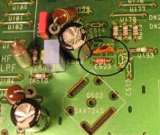
You're probably right, that display is acting real funny. Could it be the reset circuit? There's a small TO-92 device (QF02) that monitors the supply line and generates a power-on reset.
Ray.
rowemeister said:Hi
Glad you like the mods.
Your problem is not caused by the crystal.
To me its micro processor related. Check the 5V to the processor.
You may have a crack or dry joint in the pcb and this missing V rail or gnd is causing problems.
Brent
You're probably right, that display is acting real funny. Could it be the reset circuit? There's a small TO-92 device (QF02) that monitors the supply line and generates a power-on reset.
Ray.
- Home
- Source & Line
- Digital Source
- Marantz CD63 & CD67 mods list