G said:
There are a couple of the TB drivers that would seem to be perfect for these enclosures if you have the watts to push them.
can the TB W3-871S be used?
gychang
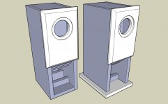
Here is the plan.
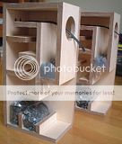
There appears to be two small pieces located in the upper mouth of the horn. I see them in finished enclosures, but they do not appear on the plan. Does anyone know the dimensions of these two pieces? I'm guessing that one is about 30mm tall, and the other is about 16mm.
now these are what i would like to see plans of. little baby desktop swans.
An externally hosted image should be here but it was not working when we last tested it.
I'm still trying to figure out the sizes for those two little pieces in the mouth of the horn. In some photos, it appears the ratio of the steps goes 4:2:1. In other photos, it seems the ratio might be 3:2:1. It is difficult to tell which is correct. I suspect the net effect on the enclosure's performance is minimal.
http://i69.photobucket.com/albums/i43/Ty_Bower/Makizou/04.jpg
http://i69.photobucket.com/albums/i43/Ty_Bower/Makizou/makizou.jpg
I suspect the width of the front of the enclosure is 156mm, and the width of the all pieces that go between the sides is 124mm. This is slightly wider than some of the other guesses mentioned above. I'm basing my suspicions on several photos of the front of completed units, but it's difficult to find a good photo which is not skewed by camera angle. My suspicion is further confirmed by the distance of the center of the driver opening in relation to the top of the cabinet. The drawings I have seen indicate the driver center is 78mm from the top. It seems reasonable to me that the center would also be equidistant from the sides of the box, which would make the whole thing 156mm wide. I'm assuming the plywood used is supposed to be 16mm thick. Can anyone confirm or deny this? Does this tiny bit of extra width really make any appreciable difference in the tuning of the enclosure?
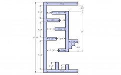
I sketched up a new dimensional drawing of the side of the enclosure. It is based primary on the drawing found earlier in this thread. I've also set out a possible layout for a single 2' x 6' piece of plywood. Perhaps if I am sufficiently inspired, I'll try to cut one of these out this weekend.
http://i69.photobucket.com/albums/i43/Ty_Bower/Makizou/Makizou72dpi.gif
http://i69.photobucket.com/albums/i43/Ty_Bower/Makizou/Materiallayout72dpi.gif
http://i69.photobucket.com/albums/i43/Ty_Bower/Makizou/04.jpg
http://i69.photobucket.com/albums/i43/Ty_Bower/Makizou/makizou.jpg
I suspect the width of the front of the enclosure is 156mm, and the width of the all pieces that go between the sides is 124mm. This is slightly wider than some of the other guesses mentioned above. I'm basing my suspicions on several photos of the front of completed units, but it's difficult to find a good photo which is not skewed by camera angle. My suspicion is further confirmed by the distance of the center of the driver opening in relation to the top of the cabinet. The drawings I have seen indicate the driver center is 78mm from the top. It seems reasonable to me that the center would also be equidistant from the sides of the box, which would make the whole thing 156mm wide. I'm assuming the plywood used is supposed to be 16mm thick. Can anyone confirm or deny this? Does this tiny bit of extra width really make any appreciable difference in the tuning of the enclosure?
I sketched up a new dimensional drawing of the side of the enclosure. It is based primary on the drawing found earlier in this thread. I've also set out a possible layout for a single 2' x 6' piece of plywood. Perhaps if I am sufficiently inspired, I'll try to cut one of these out this weekend.
http://i69.photobucket.com/albums/i43/Ty_Bower/Makizou/Makizou72dpi.gif
http://i69.photobucket.com/albums/i43/Ty_Bower/Makizou/Materiallayout72dpi.gif
According to the Sketchup model posted earlier in the thread, the internal width is 120mm.
Keep us posted. I've always liked the idea of these types of designs- not much material needed and not much space taken up. If you can get into the 75Hz range, it should be very easy to use a small sub.
Keep us posted. I've always liked the idea of these types of designs- not much material needed and not much space taken up. If you can get into the 75Hz range, it should be very easy to use a small sub.
For those looking at smaller designs, there are several for the FE83 here
http://homepage1.nifty.com/takabou/fe108e_backroad.html
http://homepage1.nifty.com/takabou/fe108e_backroad.html
For those looking at smaller designs, there are several for the FE83 here
http://homepage1.nifty.com/takabou/fe108e_backroad.html
There are loads of ideas at nifty above. But Off Topic, what is going on with that Baby Swan posted by Trooper46?
Last edited:
Here is the plan.
I keep going back to the design shown in post #6. Does it seem curious that the cross sectional area of the top piece (39mm x 120mm) is larger than the piece just below it (30mm x 120mm)?
I'm wondering if maybe all the pieces forming the resonator cavities should be shifted upwards by about 15~16mm. This would be the 85, 80, 65, 60, 45, and the 238mm pieces. In other words, the "39" measurement should be from the top side of the top piece. As it is shown, the "39" is drawn from the bottom side of the top piece.
There's another blog detailing someone's build project. His completed photos seem to show the top section smaller relative to all the others. You can find the details in the photos here:
http://networkentry.blog22.fc2.com/blog-entry-30.html
p.s. - Babelfish translation here
Another thing - I'd really like to rescale the drawing to use 3/4" (~18mm) plywood instead of 5/8" (~15mm). Around here, it's very difficult to find finish grade plywood in 5/8" without resorting to mail order.
Which dimensions are critical to the design? I'll assume the front compression chamber needs to remain at the same 1085 cm^3 that it is now. What measurement is important in the resonators? Is it the 80mm/93mm/110mm that defines how the system responds? I could simply lengthen the 238mm center piece by 6mm to account for the added thickness of the ply and keep those spacings the same, but it will result in an increase of the overall volume of the back section of the enclosure. What is the significance of the length of the 85/80/65/60/45mm partitions? Would their lengths need to change? And how about the spacing between the center piece and the back wall? Should I increase the overall front-to-back distance of the enclosure to keep that spacing the same as it is now?
Which dimensions are critical to the design? I'll assume the front compression chamber needs to remain at the same 1085 cm^3 that it is now. What measurement is important in the resonators? Is it the 80mm/93mm/110mm that defines how the system responds? I could simply lengthen the 238mm center piece by 6mm to account for the added thickness of the ply and keep those spacings the same, but it will result in an increase of the overall volume of the back section of the enclosure. What is the significance of the length of the 85/80/65/60/45mm partitions? Would their lengths need to change? And how about the spacing between the center piece and the back wall? Should I increase the overall front-to-back distance of the enclosure to keep that spacing the same as it is now?
In my not-so-professional but semi-experienced opinion, rescaling for 3/4" material doesn't have to be as painful as your making it. When drawing it just add 1/4" to overall depth for every vertical panel, and again to height for every horizontal panel. The extra length and volume added should be insignificant. If going through the trouble of scaling and re-drawing, make the CC bigger while you're at it. I have found lots of success in varying the size of CCs through experimentation, and I can always decrease the volume if I begin a little big, but not the other way around. Hell, my interest in this little guy makes me want to re-draw it. I'll whip one up quick and post it in a bit...
Here's my re-scaled version. No fair peeking until you've posted yours - I want to compare unbiased results.
http://i69.photobucket.com/albums/i43/Ty_Bower/Makizou/Makizou18mm.gif
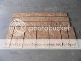
The plywood is waiting. I've got one full sheet, cut into thirds. It should be enough to build three pair of enclosures. I'm not sure what kind of wood, but it looks nice, rated AC and S2S. There doesn't seem to be much in the way of voids, either. The saw is hungry.

http://i69.photobucket.com/albums/i43/Ty_Bower/Makizou/P1120479.jpg
http://i69.photobucket.com/albums/i43/Ty_Bower/Makizou/Makizou18mm.gif
The plywood is waiting. I've got one full sheet, cut into thirds. It should be enough to build three pair of enclosures. I'm not sure what kind of wood, but it looks nice, rated AC and S2S. There doesn't seem to be much in the way of voids, either. The saw is hungry.

http://i69.photobucket.com/albums/i43/Ty_Bower/Makizou/P1120479.jpg
Last edited:
Mine's in inches, can't compare. I am pretty confident in the translation (metric to english plus added wood thickness). Plus, mine is a little different from the original that in that it provides for a removeable baffle. This also facilitates a little extra space in the CC.
Attachments
Last edited:
I keep going back to the design shown in post #6. Does it seem curious that the cross sectional area of the top piece (39mm x 120mm) is larger than the piece just below it (30mm x 120mm)?
I'm wondering if maybe all the pieces forming the resonator cavities should be shifted upwards by about 15~16mm. This would be the 85, 80, 65, 60, 45, and the 238mm pieces. In other words, the "39" measurement should be from the top side of the top piece. As it is shown, the "39" is drawn from the bottom side of the top piece.
Here's something else to ponder. Looking at this post:
http://www.diyaudio.com/forums/full-range/126296-frugalhorn-fe166.html#post1561115
It seems the opening of a typical horn should be:
throat area = (2pi * Fs * Qts * Vas) / speed of sound
If you use the specs for the Fostex FE87E, you get (2*pi*140 Hz*0.92*1030cm^3) / 34029 cm per sec = 24.5 cm^2.
If the design drawings have a 39mm tall opening to the throat, that gives 39mm * 120mm = 46.8 cm^2, which seems like it should be too much.
Any comments?
Well, first off, I don't think that this is a horn. I think it's a transmission line. So much has been said about what exactly this and that different designs are, usually coming from one of the resident experts... a TL here, a TQWP-TL there... even they concede that it ultimately not so important the title, but whether it fullfills the intended duty. We often refer to many different approaches as a horn because they look like one at first glance. I could be wrong here, but it is of little consequence if I am because...
Second, these designs, IIRC, are born of basic math and tireless trial and error. In the slightly-odd-to-us-white-guys Japaneese tradition of "these are the works of the masters, respect them or suffer the super Karate Death Car", they represent more the art of each particular design as a whole than actual output (although the sound is of high importance of course). They are sub-optimal and outdated. Why the interest, then? Well, some are drawn to... the art of the particular design as a whole. If you're looking to coax every last ounce out of any given driver, 60 minutes using Hornresp will put you a step ahead of this family of designs, and any fine-tuned, modern BLH or TL or whatever will put you leaps ahead.
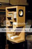
At the end of the day, building this example will give you a very fine midbass with an unusual amount of high-end extension. The magic comes from DIYing a piece in the old Japaneese tradition, and they will no doubt have a "signature sound". My interest in this one includes setting the enclosure on top of a cabinet housing a small woofer (6" or 7") doubling as a stand and then biamping. Of course, a simple "FAST" is a much easier route, but I'm a glutton for punishment...
Second, these designs, IIRC, are born of basic math and tireless trial and error. In the slightly-odd-to-us-white-guys Japaneese tradition of "these are the works of the masters, respect them or suffer the super Karate Death Car", they represent more the art of each particular design as a whole than actual output (although the sound is of high importance of course). They are sub-optimal and outdated. Why the interest, then? Well, some are drawn to... the art of the particular design as a whole. If you're looking to coax every last ounce out of any given driver, 60 minutes using Hornresp will put you a step ahead of this family of designs, and any fine-tuned, modern BLH or TL or whatever will put you leaps ahead.
At the end of the day, building this example will give you a very fine midbass with an unusual amount of high-end extension. The magic comes from DIYing a piece in the old Japaneese tradition, and they will no doubt have a "signature sound". My interest in this one includes setting the enclosure on top of a cabinet housing a small woofer (6" or 7") doubling as a stand and then biamping. Of course, a simple "FAST" is a much easier route, but I'm a glutton for punishment...
Makizou :: P1120533.jpg picture by Ty_Bower - Photobucket
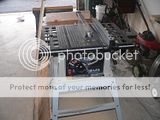
I've never used a table saw, but figured I needed one to build horn enclosures. I found this piece of junk on Craigslist. He wanted fifty, I offered forty. We split the difference. I found it awkward to use on the 32" x 48" sheet of 3/4" ply. As the sheet got smaller and I gained a little practice, it got a lot easier. Still, I think I could have done just as good a job with my circular saw and a 4' steel ruler. Or maybe I should have bought a better table saw?

Makizou :: P1120534.jpg picture by Ty_Bower - Photobucket
Makizou :: P1120536.jpg picture by Ty_Bower - Photobucket
I made my first few practice cuts on some garbage 1/2" chipboard. It was previously used as temporary decking. Remember to find all the nails and pull them out before you try to rip anything.

Makizou :: P1120537.jpg picture by Ty_Bower - Photobucket
The miter saw makes quick work of the rest. I like this machine.

Makizou :: P1120539.jpg picture by Ty_Bower - Photobucket
Makizou :: P1120540.jpg picture by Ty_Bower - Photobucket
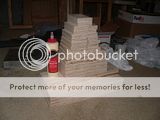
A stack of parts. It's just like playing with blocks in preschool. After this, I guess it's mostly a matter of waiting for the glue to dry. Sure do wish I had more than two clamps.
http://s69.photobucket.com/albums/i43/Ty_Bower/Makizou/P1120543.jpg
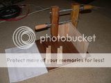
This clamp nonsense is going to take forever.

http://s69.photobucket.com/albums/i43/Ty_Bower/Makizou/P1120544.jpg
I've got lots of these SLA batteries which I've been meaning to take to the recyclery. I guess the piece of floor they've been holding down won't mind if I borrow them for a short while.
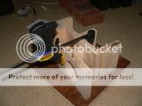
http://s69.photobucket.com/albums/i43/Ty_Bower/Makizou/P1120564.jpg
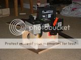
http://s69.photobucket.com/albums/i43/Ty_Bower/Makizou/P1120560.jpg
The glueing continues. Yes, it appears I'm unable to glue more than one or two pieces a day. It's OK, I'm still waiting for the drivers to arrive.
- Status
- This old topic is closed. If you want to reopen this topic, contact a moderator using the "Report Post" button.
- Home
- Loudspeakers
- Full Range
- Makizou, I finally did it.