you are absolutely right...but, the reason behind asking this was, if there is a compatible FET available which can replace two IRFZ's...then i will be saving space....
if there is a solution like that available, which wont get hot equal to two FET's ...then i would love to know.
if there is a solution like that available, which wont get hot equal to two FET's ...then i would love to know.
just tested 6 of IRFP064 at the place of 12 IRFZ44....and found out that IRFP064 get way more hot then using 12 IRFZ44....
I should have followed what you said, but, since i had them...so, i thought - lets try it.
is there option where I can save board size by reducing the FETz and getting the same power ?
I should have followed what you said, but, since i had them...so, i thought - lets try it.
is there option where I can save board size by reducing the FETz and getting the same power ?
If you're going to drive the transformers from separate groups of FETs, I don't think you can go lower than 12 FETs (your only option would be 6 FETs). If you were going to drive all of the primaries in parallel, you may be able to use 8 or 10 IRF3205s but that wouldn't save much space.
What gate resistors are you using (100 ohms, 47 ohms...)?
What gate resistors are you using (100 ohms, 47 ohms...)?
gate resistance is 100 ohm... (where will it effect if I use 47 ohm) ?
as you can see in the picture....i was using 12 mosfets to drive 3 primaries in parallel...
is it ok to use 3 primaries in parallel and use 8,10 or 12 mosfets ? (i mean technically, is it right to use primaries in parallel?)
as you can see in the picture....i was using 12 mosfets to drive 3 primaries in parallel...
is it ok to use 3 primaries in parallel and use 8,10 or 12 mosfets ? (i mean technically, is it right to use primaries in parallel?)
While I believe that the Z44s are a better option, the 064s should not be running significantly hotter. This may indicate that there are other problems with the drive circuit.
You could try increasing the dead time slightly. That should help if shoot-through is the problem.
What are you using as a buffer between the 3525 and the FETs?
If you're trying to drive the FETs directly from the 3525 with no buffer, that could be part of the problem.
You could try increasing the dead time slightly. That should help if shoot-through is the problem.
What are you using as a buffer between the 3525 and the FETs?
If you're trying to drive the FETs directly from the 3525 with no buffer, that could be part of the problem.
Hi
Your Rgate should be as low as possible, but high enough with xx dead time to create good waveforms
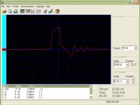
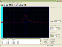
See how primary side waveform should look like

Can you see, ramp, it is going down slowly, then last part is fast...here you can see too little dead time, since ramp didn't go all the way down and you should in the end get something like this

Your Rgate should be as low as possible, but high enough with xx dead time to create good waveforms
See how primary side waveform should look like
Can you see, ramp, it is going down slowly, then last part is fast...here you can see too little dead time, since ramp didn't go all the way down and you should in the end get something like this
Perry Babin said:While I believe that the Z44s are a better option, the 064s should not be running significantly hotter. This may indicate that there are other problems with the drive circuit.
You could try increasing the dead time slightly. That should help if shoot-through is the problem.
What are you using as a buffer between the 3525 and the FETs?
If you're trying to drive the FETs directly from the 3525 with no buffer, that could be part of the problem.
I was not using any buffer...now, i have added BD139/BD140 buffer...
the results are a bit better....now, the mosfets get hot but, takes a little time to get hot...
i am driving 6 mosfets with 3 transformers....and taking 430-watt of output from them.
luka said:Hi
Your Rgate should be as low as possible, but high enough with xx dead time to create good waveforms
See how primary side waveform should look like
Can you see, ramp, it is going down slowly, then last part is fast...here you can see too little dead time, since ramp didn't go all the way down and you should in the end get something like this
Here is what i see at the output of SG3525....
notice that one output is different then another.....
I have no clue on why its like this....it should be equal...right?...
Help ! (Perry & Luka)
Attachments
Perry Babin said:While I believe that the Z44s are a better option, the 064s should not be running significantly hotter. This may indicate that there are other problems with the drive circuit.
You could try increasing the dead time slightly. That should help if shoot-through is the problem.
What are you using as a buffer between the 3525 and the FETs?
If you're trying to drive the FETs directly from the 3525 with no buffer, that could be part of the problem.
Perry,
I have increased the dead-time.....and replaced 100-ohm resistance with 220-ohm
results are much better then before !!
heat is much less then before...
any more suggestions based on the scope output ?
The schematic seems to be OK. You simply need a good buffer.
For each buffer, do you have...
the collector of the NPN connected to 12v?
the collector of the PNP connected to ground?
the bases of the two transistors connected together and connected to the output of the 3525?
the emitters of the two transistors connected together and connected to the gate resistors of one bank of FETs?
- Status
- This old topic is closed. If you want to reopen this topic, contact a moderator using the "Report Post" button.
- Home
- General Interest
- Car Audio
- Making car amplifier SMPS with tl494 + DC Protection