Thanks Perry, I will check it out in the morning....
i did some more tries....
i was using standard capacitors on the input.....
i have changed these capacitors to low esr capacitors...and found that the voltages are gained by 1.5 volts...
so, i have gained 1.5volts by using ESR capacitors....but, still need couple of more volts.
is there any more tips/tricks like this one i can do to regulate the output voltages?....
There's not much difference between the reg for a 352x and the 494.
What are you using for a regulator now (schematic)?
Does your amplifier have one end of the secondary tied to ground or is it floating?
If it's not tied to ground, are you using a bridge rectifier for the output?
What are you using for a regulator now (schematic)?
Does your amplifier have one end of the secondary tied to ground or is it floating?
If it's not tied to ground, are you using a bridge rectifier for the output?
For the 494, reverse the connections for the two inputs of the error amplifier (pins 1 and 2). The (-) input will be connected to the voltage divider. The (+) input will be connected to the opto-coupler.
On the 494, you'll have to tie pin 15 to pin 14 and you'll have to ground pin 16.
Why are you changing the drive IC? The 3525 is a good IC.
On the 494, you'll have to tie pin 15 to pin 14 and you'll have to ground pin 16.
Why are you changing the drive IC? The 3525 is a good IC.
cool...thanks !
actually, i am facing voltage drop.....to cover the voltage drop, i have to wind extra 20v winding (about 5-6 extra turns)....and then it works fine and regulated without any drop on 650-watt load.
i have seen tl494 used in DU700 (from powerstream.com) its a 12v to 36v converter....
where they are using it as boost converter...using it with 3 irfz44 and the output is parallel...
on a full load, there is not a single volt drop on it....so, i thought...maybe its a good option....
if by winding extra turns, i am not abusing anything in the circuit, then i definitely dont have any problem...
what do you think?
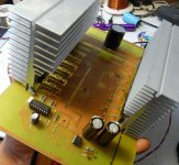
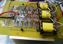
here is what i am doing.....its on a proper pcb...with perfect heatsinks...
at the moment, i am using 3 transformers....from another smps....and using the output of them in series which produces 70v....and then regulating them on 44v....
this setup is working just fine....without a 0.1v drop....
as you said, i am using 12 irfz44s....
at the moment, i am using the primary of all 3 transformers in parallel...but, i am gona divide 12 mosfets in a group of 4 for each transformer and use the output in series from all 3.
I have tested this setup on 650-watt of load and the mosfets are just a little warm....
except on that load, i hear a high-frequency sound....
i am using 30khz of pwm from sg3525..
i have actually used the same pcb design and modified it in photoshop to add more mosfets in the same line....
what do you think?
Attachments
I didn't realize that you made a board for it.
The noise could be from instability in the regulator. A capacitor across the output of the opto-coupler may help. You could also try capacitive feedback (0.01uf? - experiment) from the inverting input to the comp pin. Too much capacitance will slow the reaction time of the regulator (may not be a problem for your application). Too little capacitance would not stabilize the reg.
Maybe you can get Eva to help here.
When properly designed, there will be very little power dissipation in the transistors of a switching power supply. The power rating is not a significant factor in choosing the FETs.
Two Z44s are probably a better option. The Z44s are cheaper. Two Z44s would likely be more rugged than 1 IRFP064. They can handle more current. The heat could be dissipated better by two Z44s. They will produce about the same heat as a single 064 but the heat can be dissipated at two points on the sink instead of one.
Two Z44s are probably a better option. The Z44s are cheaper. Two Z44s would likely be more rugged than 1 IRFP064. They can handle more current. The heat could be dissipated better by two Z44s. They will produce about the same heat as a single 064 but the heat can be dissipated at two points on the sink instead of one.
- Status
- This old topic is closed. If you want to reopen this topic, contact a moderator using the "Report Post" button.
- Home
- General Interest
- Car Audio
- Making car amplifier SMPS with tl494 + DC Protection