You could always put a screw terminal on the "DC in" pads, so you could use bare wires from your wallwart.
However, for testing purposes, use a pair of 9v batteries. Or a tray of 12 batteries... Actually, if you found a tray that could hold 12 AA (LR6) batteries, you would probably have to replace them every 6 months or so....")
However, for testing purposes, use a pair of 9v batteries. Or a tray of 12 batteries... Actually, if you found a tray that could hold 12 AA (LR6) batteries, you would probably have to replace them every 6 months or so....
You could always put a screw terminal on the "DC in" pads, so you could use bare wires from your wallwart.
However, for testing purposes, use a pair of 9v batteries. Or a tray of 12 batteries... Actually, if you found a tray that could hold 12 AA (LR6) batteries, you would probably have to replace them every 6 months or so....
I was thinking a screw terminal like in the stock foto.
I was thinking a screw terminal like in the stock foto.
Exactly what I was trying to say!!
You could always put a screw terminal on the "DC in" pads, so you could use bare wires from your wallwart.
Wouldn't it be more safe to use insulated wires, rather than bare wires?
Nice build
Yeah I'll be using insulated wires. I like excitement, but not so much
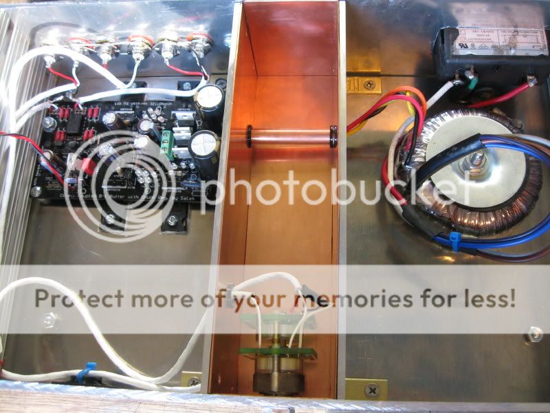
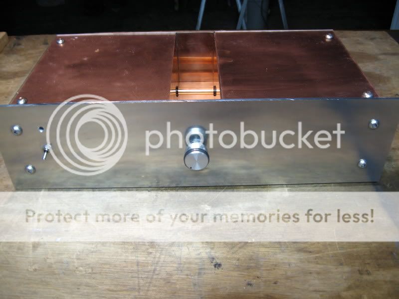
Sent the plans for the chassis to a buddy yesterday, so there's no turning back. There's no room for a toroid in it, so it's going to be a wallwart and no on/off switch. Pretty much stock except for the caps and resistor types. I wanted all the resistors from the same series to, but that could'nt be done without ordering from a few different places....
If this works, then next time I want to experiment more with different solutions, but for my first build I didn't want to complicate stuff to much.
The cutouts are for toggleswitch + Alps or TKD pot. I figured they'll both fit regardless...
So now I am hunting for nice wood panels for the sides
Yeah I'll be using insulated wires. I like excitement, but not so much
Sent the plans for the chassis to a buddy yesterday, so there's no turning back. There's no room for a toroid in it, so it's going to be a wallwart and no on/off switch. Pretty much stock except for the caps and resistor types. I wanted all the resistors from the same series to, but that could'nt be done without ordering from a few different places....
If this works, then next time I want to experiment more with different solutions, but for my first build I didn't want to complicate stuff to much.
The cutouts are for toggleswitch + Alps or TKD pot. I figured they'll both fit regardless...
So now I am hunting for nice wood panels for the sides
Wouldn't it be more safe to use insulated wires, rather than bare wires?
I was thinking about removing the plug from the output of the wallwart, putting it through a small hole in the chassis, stripping a bit of the wire's insulation, exposing about 2mm of bare copper, and connecting it in the screw terminal.
Only because there was some difficulty in sourcing and selecting a chassis-mount female plug to mate to the wallwart.
Not a bad idea. I think I got the plug-in covered though. The supply I am getting is universal voltage with a set of different plugs
I was thinking about removing the plug from the output of the wallwart, putting it through a small hole in the chassis, stripping a bit of the wire's insulation, exposing about 2mm of bare copper, and connecting it in the screw terminal.
Only because there was some difficulty in sourcing and selecting a chassis-mount female plug to mate to the wallwart.
Personally, I think the "bare wires" concept would have been a lot more intriguing/exciting/stimulating/hazardous!
I am searching digikey right now looking for som standoffs for my B1, but haven't a clue what size to get. Can anyone please point the way?
Is there any kind of assortment to get, or do I have to get each one a specific size?
And while we're talking standoffs, I want to get some for my dac/headamp project at the same time. SO if anyone here has built the PIMETA and the AlienDAC I wouldn't mind a standoff tip for those either. I am also lost as to how to fasten the crossfeed pcb on top of the pimeta. Some spacers came with the pcb, but what size bolts and screws do I need to fasten it?? my searches come up empty, so I hope someone can take a couple of minutes to help me out.
Btw, does anyone have any experience with FPE and the housing profiles? I am trying to make an enclosure, but the only thing I get right is the front panel, and that's not even complete. Don't know how to make the holes for the screws...to much technical jargon for me to wrap my head around....
I use these from Farnell; available in various lengths;
HARWIN|R30-3001002|SPACER, M-F, 10MM, PK25 | Farnell United Kingdom
HARWIN|R30-3001002|SPACER, M-F, 10MM, PK25 | Farnell United Kingdom
Yes,
an accurate 8.9mm hole is probably enough.
You may find that the 8.9mm threaded bushing is the actual measurement over the top/peaks of the threads of a 9mm metric thread.
However many of these bushing are cast and thus not quite round.
Some have a flat in the threads, sometimes two flats or even a slot through the threads. This is to stop the bushing turning if an operator forces the knob round.
Wait till you see what the bushing looks like before buying a 9mm drill. You may have to drill very much undersize and shape the hole to fit the bushing.
I finally found the right toggle switches
If it says 8.9mm threaded bushing, but how big do I have to make the hole? is 9mm enough?
Best thing is to buy a set of drill bits which usually range in size from 1-12mm which means you will have everything covered including the phono socket holes.
Certainly more practical, yes. I'll se what I do, maybe borrow a drill and get the bits or get modu/FPE to do the work. Would be nice with some engraving to, you know
Finally sorted my volumepot aswell. I figured I didn't want to spend $100-$150,- on TKD or Goldpoint, even if the resistance is spot on with a 25k GP. I found a PCB for the Alps RK27 which makes soldering the pins more doable for me. So I think I am going for that one. Put's the cost of the pot at $37 shipped.
It's definately not the last thing I build, so I figured I can spend more money later on, when I am more confident at what I am doing.
- Status
- This old topic is closed. If you want to reopen this topic, contact a moderator using the "Report Post" button.
- Home
- Amplifiers
- Pass Labs
- MagnumOpus & The B1