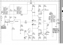
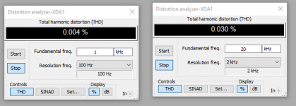
See 0.004 and 0.03 and this is with 100pF compensation.
With 30p the distortion is 0.003 and 0.014 : veeeery good for a clean ltp circuit.
Its because the feedback needs more current.
I think 100p compensation is needed only with current mirror.
I think this way its better than current mirror loading.
With a current mirror I get 0.009% @ 20khz with this output stage but Its not worth the risk. 0.030 is plenty enough.
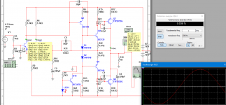
I forgot to mention: the load is 6 ohms and the Vrms is 3V with supply +-12V
Just tried: the distortion is 0.030 @ 6V rms , 20khz and 30p compensation cap.
With 30p the distortion is 0.003 and 0.014 : veeeery good for a clean ltp circuit.
Its because the feedback needs more current.
I think 100p compensation is needed only with current mirror.
I think this way its better than current mirror loading.
With a current mirror I get 0.009% @ 20khz with this output stage but Its not worth the risk. 0.030 is plenty enough.
I forgot to mention: the load is 6 ohms and the Vrms is 3V with supply +-12V
Just tried: the distortion is 0.030 @ 6V rms , 20khz and 30p compensation cap.
Attachments
Last edited:
Conventional wisdom actually says the leg with the VAS on it needs more current, but I suspect there may be some distortion cancellation going on. That or external impedance levels.
R2 may benefit from some bootstrapping action here or going CCS altogether.
Why do you have both a bootstrapped collector load and a CCS in parallel? What's the reasoning behind that?
You should really use some more sophisticated biasing than the two diodes (like ther usual Vbe multiplier), controlling output stage quiescent current is a real pain like that. A capacitor over the bias should also improve HF THD.
Its because the feedback needs more current.
I think 100p compensation is needed only with current mirror.
The compensation is more related with stability, which is a function of a lot of things. If you can achieve stability without it, then don't use it as it is an extra load for the previous stage (LTP).
I'm not sure, but I think it is not about whether -in must get higher current than +in. Often the +in must have low (not lower) current when there is no ccs (because current is shared). Certain transistors work better with less than 1mA current too (the current is to make sure a class-A operation only).
Eww... I have never seen feedback resistor as small as 1k8 for this topology (that's why the high current). I think stability is the issue with such high current feedback.
Last edited:
> Conventional wisdom actually says the leg with the VAS on it needs more current, but I suspect there may be some distortion cancellation going on. That or external impedance levels. R2 may benefit from some bootstrapping action here or going CCS altogether.
No, the more current must be at the feedback EF because the circuit is more faster this way. There are always a parasitic capacitances that we want to kill and this is the way: low impedance feed stages! And high impedance sense ones.
The feedback goes from emitter 2 to emitter 1 and driveing emitter 1 is like driving a common base amplifier which have low input impedance and needs some boost.
This is not the case: I need exactly x ohms output impedance because I dont need more current.
This is the case: I need infinite low impedance because more is never enough -> more current, faster charge the transistors capacitances
Also low impedance means less noise too!
Its very time consuming to open datasheets and calculate this..
Where is the deal when its not problem to run the EF transistor @ 100-200mW
The transistor must be little warm when u touch it.
> Why do you have both a bootstrapped collector load and a CCS in parallel? What's the reasoning behind that?
Because I experimented with both and liked their sound.
They both good but sound different and I think it will be a very good synergy if I mix them. I can't wait to test that.
If I have to choose I will choose the bootstrap because very like its bass.
It makes the bass very soft and warm (maybe changes its phase curve).
> You should really use some more sophisticated biasing than the two diodes (like ther usual Vbe multiplier), controlling output stage quiescent current is a real pain like that. A capacitor over the bias should also improve HF THD.
This schematic was only for demonstration, I made it in seconds.
-----------------------
> The compensation is more related with stability, which is a function of a lot of things. If you can achieve stability without it, then don't use it as it is an extra load for the previous stage (LTP).
Exactly, its a function of things and thats why u must use it everywhere u have high gain VAS. Its possible to be stable a long time and then suddenly -> "magic smoke" from the output stage.
Maybe the key to comp-less design is to use less gain VAS and a very low impedance feeder/inverter that keeps it strongly biased.
This have another + too: the circuit will work like in the simulator because of the high vas emitter resistor.
Maybe we dont need that much gain.
Also its better to run the input stage from higher power supply which is not a problem at all.
As we know its slew rate is faster at small swings.
> "..because current is shared.."
This depends from how you bias it (the load resistor)
Change it that so the more current goes to the right leg and see the result.
> Certain transistors work better with less than 1mA current too (the current is to make sure a class-A operation only).
Its better to have low impedance stages everywhere because they charge fast the capacitors, kill noise and keeps things stable.
> Eww... I have never seen feedback resistor as small as 1k8 for this topology (that's why the high current). I think stability is the issue with such high current feedback.
Its better to be low as i mentioned : fast capacitor charge, noise kill, keeps stable, faster slewrate.
Last edited:
Its better to be low as i mentioned : fast capacitor charge, noise kill, keeps stable, faster slewrate.
Yes, lower usually sounds better. But is it possible? Stability? DC offset?
Yes, if it sounds better ")
-----------
ilimzn, I like this way because outputs are VAS stages and the gain is less this way, makes it more stable.
-----------
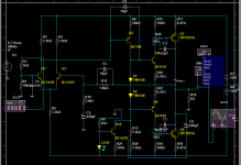
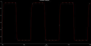
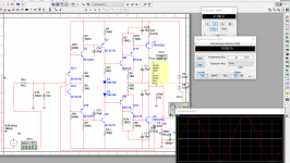
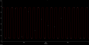
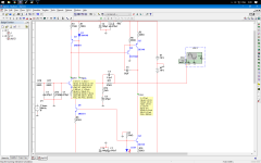
Look what I made today, Its very stable at square wave without compensation caps.
I think this topology hates these caps because in one of my tries it oscillated with C10 and C11
I removed them and everything went fine.
This topology is my favourite because u dont need an emitter follower to amplify the current of the feedback when u have power resistors and infinite current from the output stage..
The THD is the same with all comp caps connected. Also notice that there is 6 ohm load attached.
0.008% @ 20khz with 6 ohms and maybe this is limited from the feedback impedance.
capacitors doesn't play role here because i use high current.
Look how I kill Q7 and Q14's capacitors.
-----------
ilimzn, I like this way because outputs are VAS stages and the gain is less this way, makes it more stable.
-----------
Look what I made today, Its very stable at square wave without compensation caps.
I think this topology hates these caps because in one of my tries it oscillated with C10 and C11
I removed them and everything went fine.
This topology is my favourite because u dont need an emitter follower to amplify the current of the feedback when u have power resistors and infinite current from the output stage..
The THD is the same with all comp caps connected. Also notice that there is 6 ohm load attached.
0.008% @ 20khz with 6 ohms and maybe this is limited from the feedback impedance.
capacitors doesn't play role here because i use high current.
Look how I kill Q7 and Q14's capacitors.
Attachments
Last edited:
You mean to tell me that the better is impossible ?
Every other design I tried in the simulator oscillated as hell with 20khz squares.
VERY IMPORTANT: You can't disconnect the feedback from the ground at DC as you can with LTP and a 220u cap.
The whole circuit doesn't work when u disconnect it.
Actually only LTP+current_mirror seems unstable.
You need compensation without current mirror too but at least u can be sure that it wont oscillate.
I very liked current mirrors before but no more like them. They seem to me very unstable. oscillating and unreliable.
You can get the same THD without it if you think how to do it.
The nature have invented the things very well and its easy to study them.
Last edited:
You mean to tell me that the better is impossible ?
Every other design I tried in the simulator oscillated as hell with 20khz squares
I mean if such circuit can work as promised in reality, not just simulation.
I know what u think but its untrue:
You think that if u use high current stages, the current goes RF and make the circuit unstable.
Its true but its untrue because the low impedance stage keep the next one very strong and tight and this effect is greater than the 1st one u think.
High impedance - high sensitivity, bad stability.
Low impedance - good stability, rock solid.
Ofcourse u cant go infinite low, You go max possible.
Worse
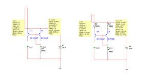
edit: I saw that the results in my 1st post were with lower Vrms, with 100p comp and without C6
Resimulated and it gives me 0.030% which is worse again when compared to mine in the 1st post.
You think that if u use high current stages, the current goes RF and make the circuit unstable.
Its true but its untrue because the low impedance stage keep the next one very strong and tight and this effect is greater than the 1st one u think.
High impedance - high sensitivity, bad stability.
Low impedance - good stability, rock solid.
Ofcourse u cant go infinite low, You go max possible.
Hi,
try to change the R2 to 15k.
Sajti
Worse
edit: I saw that the results in my 1st post were with lower Vrms, with 100p comp and without C6
Resimulated and it gives me 0.030% which is worse again when compared to mine in the 1st post.
Attachments
Last edited:
Actually only LTP+current_mirror seems unstable.
You need compensation without current mirror too but at least u can be sure that it wont oscillate.
I very liked current mirrors before but no more like them. They seem to me very unstable. oscillating and unreliable.
Very easy to make LTP with current mirror stable, if you understand how to compensated it. Compensation can be done in many way. You can use ordinary miller, two pole compensation, transition miller compensation, miller input compensation, etc.
I design many amplifiers using LTP+current mirror. The first prototype was never oscillated.
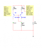
Well, this means current mirror with gain is the best option.
In this example I have 900uA in the left and 1.6mA in the right.
Gives 0.0003% THD at 20khz
If you want to achieve 0.000000%, use a trimmer instead R3, watch/hear with an analyser/ear and adjust.
Its very important to connect C5 as I connected it.
In this example I have 900uA in the left and 1.6mA in the right.
Gives 0.0003% THD at 20khz
If you want to achieve 0.000000%, use a trimmer instead R3, watch/hear with an analyser/ear and adjust.
Its very important to connect C5 as I connected it.
Attachments
Last edited:
I dont know how to calculate that.
I found this http://wolfweb.unr.edu/~fadali/ee370/PM_GM.pdf
but its too deep&complicated for me.
I found this http://wolfweb.unr.edu/~fadali/ee370/PM_GM.pdf
but its too deep&complicated for me.
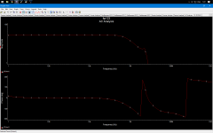
All you need is a Bode plot of open-loop gain and phase, then you can read off both directly as shown in the first slide on page 3. Obtaining such has been discussed here a few times, search for "Tian probe" and the like. For advanced understanding, the odd control theory lecture is recommended.
You could also try taking a shortcut though. Decrease R12 to maybe 0.1 ohm and increase C8 to 470 mF or so in return, which would essentially force the circuit to run open-loop at AC while DC gain remains unity (which is important to keep things from latching up). Then run an AC analysis over that. The result should be a decent approximation of an OLG plot, especially up there where you need it... if you take out the input filtering, that is.
You could also try taking a shortcut though. Decrease R12 to maybe 0.1 ohm and increase C8 to 470 mF or so in return, which would essentially force the circuit to run open-loop at AC while DC gain remains unity (which is important to keep things from latching up). Then run an AC analysis over that. The result should be a decent approximation of an OLG plot, especially up there where you need it... if you take out the input filtering, that is.
- Status
- This old topic is closed. If you want to reopen this topic, contact a moderator using the "Report Post" button.
- Home
- Amplifiers
- Solid State
- LTP works better with more current in the right collector