any reason not to try configuration, but with irfp240/9240 as output fet, in conjunction with higher pre rails and r9,23,24, changed for proper bias and gain?
...though input jfets might not like higher rails that much...
HI
BC bjt are enough to drive two mosfet pushpull ?
thanks
HI
on this schematic :
http://www.diyaudio.com/forums/atta...81d1389298492-lsk-pre-baf-2013-lskpre_fol.jpg
on this schematic :
http://www.diyaudio.com/forums/atta...81d1389298492-lsk-pre-baf-2013-lskpre_fol.jpg
Juma, I hope all has gone well with with your move to Berlin and you are all settled in. I, along with many others, appreciate all the suggestions you have given. I need a preamp with gain and a buffer. I want to use a +-24VDC supply. About 12 to 15 db should be enough gain. I started with the BJT gain stage of post #101 and adapted it to 24 V from the gain stage in #118. I got the buffer from #66. I attached below. When you get some time, would you please offer any suggestions?
Attachments
Hi propitious,
I didn't got the time to work further on that circuit so I can not offer any new suggestions but it'll do very nice as it is. Practical build will show if some additional adjustments are needed - current ranges of CCS and thermo coupling but those details are alredy known.
I didn't got the time to work further on that circuit so I can not offer any new suggestions but it'll do very nice as it is. Practical build will show if some additional adjustments are needed - current ranges of CCS and thermo coupling but those details are alredy known.
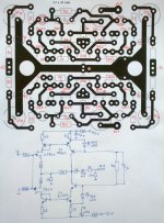
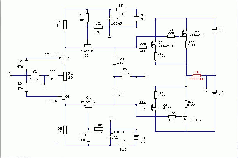
I played with the idea to use the current mirror instead of resistor/CCS in the BAF 2013 preamp circuit and I protyped attached circuit. Besides current mirror I decided to introduce the feedback loop (R7/R6, sets the gain to about 3,5V/V i.e. 11 dB).
The preamp now sounds (I think) a little bit better, the Zout is lower (about 270R, due to the feedback) so the bufer is not needed for most of the systems.
DC offset is behaving better too. With +/-12V PSU this pre will swing about 10V_peak at the output.
I used the JFETs with Idss of 7.5 and 9 mA and after setting the DC offset with P1 the Id through them is about 7mA and 11mA flows through the folded cascode (Q6/Q7). JFETs with other Idss values can be used but then R3/R5 have to be changed in order to set at least 10mA through Q6/Q7 (there is also about 1 mA going through LEDs).
Anyway, I think it's worth a try.")
The preamp now sounds (I think) a little bit better, the Zout is lower (about 270R, due to the feedback) so the bufer is not needed for most of the systems.
DC offset is behaving better too. With +/-12V PSU this pre will swing about 10V_peak at the output.
I used the JFETs with Idss of 7.5 and 9 mA and after setting the DC offset with P1 the Id through them is about 7mA and 11mA flows through the folded cascode (Q6/Q7). JFETs with other Idss values can be used but then R3/R5 have to be changed in order to set at least 10mA through Q6/Q7 (there is also about 1 mA going through LEDs).
Anyway, I think it's worth a try.
Attachments
Hi all 
I'm trying to start twice lsk with power supply ( GB Prasimix) and can not.
The power supply seems to work well. LSK on gives 32,5-33v and 22,5-23v on load.
In P1 / P4 there 0v measuring r6 and r33.
The problem is that at the output there is much fluctuation of mV. I short input.
The Lsk this on a wooden board and if I measure the output gives me very different values depending on:
If I touch probe multimeter
if I approached his hand to lsk
if I touch the multimeter to scale
if I measure with another multimeter to Once the voltage of the power supply
etc.
The difference is several hundred mV. I wonder if I have to connect any ground ... for now LSK is connected to the processor (2x 0-18) nothing more.
Thanks!
It looks OK.albertob said:Hi Juma
I'm in the final !!
I've ridden the LSK (buffered) with pcb praximix GB. It seems that all is well. I put 1k in R9 to lower the gain of the LSK. I also had to adjust R21 to have more bias.
The point is that in the output connectors have stable below 10mV. I tried to listen and there are too much background noise. The noise depends very much on the position of the cable running from the LSK output to the input of stage F5, is like an antenna.
While in there 10mV output connectors, if I connect an RCA cable there are 150 mV. Only by connecting the cable. Do I have to adjust the LSK with the cable connected?
I've seen his construction in the post 66 and see green resistors in the output of your preamp.
Say I've placed a 10K pot direct to LSK input and output (buffer) goes straight to F5. This all mounted on a wooden board for testing.
Not yet evaluated the sound. I'm testing in a small audio
Thank you for your help.

The green resistors at the output are R18 (15 Ohms).
You just have to sort out the wiring. When everything is in the open space (wooden board) you can expect all kinds of external influences. Final adjustment should be done when all is packed up in the enclosure.
Cheers !
The green resistors at the output are R18 (15 Ohms).
Can you tell me to put it is there ?, I do not see very well how it connects.
My questions may seem obvious but my knowledge is small
THANKS!!
Put R18 exactly as shown in the schematic - between the buffer's output and the RCA output terminal. Their task is to isolate the cable capacitance.Can you tell me to put it is there ?, I do not see very well how it connects.
My questions may seem obvious but my knowledge is small
THANKS!!
Put R18 exactly as shown in the schematic - between the buffer's output and the RCA output terminal. Their task is to isolate the cable capacitance.
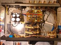
I forgot to put the pictures of the lovely preamp from the post #485 so here they are.
You'll notice that emitter resistors in current mirror differ from one schematic to another (it's the same gain stage used in Cubie2 amp). That's because the current through JFETs depends on their Idss and it can vary wildly since all grades can be used here (GR, BL, V - only important thing is that both JFETS should belong to same grade). At the same time we want the current through Q6, Q7 to be in range from 12 to 15 mA (depending on PS voltage, +/-12 to +/-18V which will cover all the usual needs, except driving the F4 to full power). To achieve that, current mirror emitter resistors have to be chosen in accord with JFETs at hand.
I didn't bother to null the DC offset - I don't mind using the coupling cap here. Of course, you can use 20 R trimm pot instead of JFET source resistors and add the P3 (known from F5 sch.) to set the prefered "harmonic structure". The trick with small trimm pot in current mirror (see Cubie 3 sch.) can also be used - it's all about experimenting, testing and finding what one likes the most...
Attachments
I have a complete kit for sale.
Unfortunately life happened and I don't have the time to get involved. Plus there is another project in the works...
If interested please see: http://www.diyaudio.com/forums/swap-meet/287466-clearance-sale-all-kinds-stuff.html
Unfortunately life happened and I don't have the time to get involved. Plus there is another project in the works...
If interested please see: http://www.diyaudio.com/forums/swap-meet/287466-clearance-sale-all-kinds-stuff.html
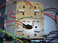
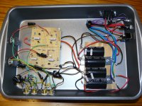
I think it is important for Mr Pass to know that there are some cheap diy'ers building the designs he has went to the trouble of providing for the diy community. I just finished building this linestage following the schematic and instructions at the BAF 2013 to go along with my just finished V-fet amplifier. I used an Antek AS-1232 100VA 32V rail transformer and just a typical FW PS using 20K uf for each rail in a CRC fashion. No regulated PS. My voltages were 46V unloaded. I used some of the LSK J-fets I bought last year matching them as close as possible with the 8 in the set for each one you purchase in our store. I was pretty close to the 15 iss value with most matches within .1 tolerance. It sounds fantastic. Carol Kings voice never sound better. I have not done any comparisons yet being I just fired it up this morning. The build was pretty straight forward on the protoboard which is not my most favorite way to build. I can get confused going from installing on top and hooking up on the bottom but this build did not give me any problems other than forgetting to hook up the pots to begin with. They go on the output which differs from the usual setup and I forgot about them. I usually work from the input then pots on back.
Attachments
I do have one question. What value pot is considered correct for this build. I thought I had read at one time 10K was what was suggested. I use 2 pots to have some balance control, my listening position is off to one side, and I just used what I keep in stock some 250K and there is too much turning with nothing much happening before I get it balanced correctly. I realize I do need to some lower resistance pots.
I now realize I should have said perfboard instead of protoboard. The picture tells the story though.
I now realize I should have said perfboard instead of protoboard. The picture tells the story though.
Last edited:
always use 10 to 25K , lower the better , if source can handle
that's best compromise between load to preceding stage (source) and output impedance of pot itself
value of pot isn't much preamp's thing ; as noted - source (loading of ) and input impedance of next stage (preamp) , along with stray/not stray capacitances ........
remember tone control action , volume pot having in yore (not best) tube preamps?
that's highish pot value , in conundrum with nanofarads ......
I decided this morning to move the pots to the input just to see.... In my opinion this is where they need to be. I like it much better this way. I also installed a couple of 4uf film caps to the power supply just because. I plan to compare this pre to my BA'3 one in the future. Last night I did a brief comparison, this is before the pot change, and I thought the BA'3 had a warmer sound. I do not have any way to measure the 2nd harmonic of each one so it is not a fair comparison.
I can say with my new V-fet it sounds great. My first thought was the bass was tighter and stronger with this pre, probably just in my head.
I can say with my new V-fet it sounds great. My first thought was the bass was tighter and stronger with this pre, probably just in my head.
- Home
- Amplifiers
- Pass Labs
- LSK pre - BAF 2013