Not sure yet. I really don't want to tear it all back down because I have a few other projects going on right now. I'm thinking defective cap that shorted or maybe a solder joint I missed since it's a dual sided PCB. I wonder if the op amps over drove the tripath and caused failure?
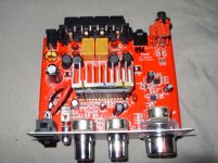
Greetings all, just signed up to say thanks for the awesome board. The wiki for the LP-2020A looks amazing, exactly what i needed. I've ordered myself a unit from here with the board in the pic inside. I hope this is a decent version! If not i can probably cancel it before Monday...?

This'll be my first audio project, and i'm looking forward to getting my teeth into it
This'll be my first audio project, and i'm looking forward to getting my teeth into it
I had this thing running for a very long time at high volumes and now the amp goes into protection mode flipping the relays anytime over 1/4 volume.
Is it possible that the low-temp rating of the op amps was to blame? I really have no idea.
In audio quality terms, how much difference does it make using more expensive dual op amps?
I wonder if the op amps over drove the tripath and caused failure?
Due to failure of other components, you mean? Is it possible that the low-temp rating of the op amps was to blame, and they're cooked? What effect does upping the power supply cap have on the overall power going through the tripath, is it possible to damage it that way? Not that i have any real idea, just curious...
In audio quality terms, how much difference does it make using more expensive dual op amps?
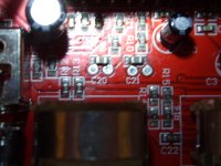
Hi. On the through-hole parts...do these need to be soldered on both sides of the board? Sorry for a silly q. Also, on my board, c20 and c21 are surface mounts. I assume I can replace with through hole as the holes are still on the board.
Thoughts?
Thoughts?
An externally hosted image should be here but it was not working when we last tested it.
Genuine Tripath chips were acknowledged to be Fragile.
The Tripath data sheet circuit produced surprisingly good Amps.. When using Genuine parts.
Cheap Chinese 'imitations' are lucky to even work.
Deleting the entire Tone nonsense off the red lep[ai board Improves sounds.. But then it remains as uncertain how long the excreable thing will function for Hours ? Weeks? A Month?
Realise that this was a foolish 20$ purchase and move on... there are Much better Chippy amps.
OK...One more time...anyone...
Cc0 and C21 are surface mounts on my board. I have two sets of replacement caps...anyone want to chime in on their experiences or thoughts???
I have a pair of Panasonic 2.2 50v bipolar electrolyte caps, Mouser# 667-ECE-AiHN2R2U
I have a pair of Wima Film Caps Mouser # 505-MKS22.2/50/5
Don't be shy...
Thanks,
D
The surface mount caps I replaced by bending and trimming leads to just fit the pad. I bent the tip of the leads so they say flat to the board then hit it with solder. The through hole ones were easy to solder both sides. I basically put a dab of flux nearest to the cap then soldered from under. The solder gravity fed to the top side and flux attracted it further.
However, it appears that your specific board has surface mount and also to through whole mounts that might be linked in so you could easily remove the surface and use a through hole component instead
However, it appears that your specific board has surface mount and also to through whole mounts that might be linked in so you could easily remove the surface and use a through hole component instead
Is it possible that the low-temp rating of the op amps was to blame? I really have no idea.
In audio quality terms, how much difference does it make using more expensive dual op amps?
The operational amplifiers that I used were close to what was originally in there, they did give a slightly better sound to my ears however I'm not exactly sure if it matters to replace them at all. And as far as considering them expensive they were only a couple dollars so not really.
... there are Much better Chippy amps.
For $20? Can you provide some links?
For $20? Can you provide some links?
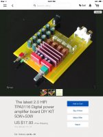
Look for the tpa3116 chip amps, they start around $12 and up on eBay
Look for the tpa3116 chip amps, they start around $12 and up on eBay
They're all good? Or the chip is good, and the cheaper boards are ok?
Cheap boards are going to be laid out with cost to a minimum regardless from whom you source the unit. The chip used is generally used in car audio amplifiers because of the power output and low noise.. Depending on what you want to do with the chip amp will determine what board design to look for. The units on eBay I mentioned will be mono bridge, stereo, and 3 channel. The chip itself can handle much higher voltage than the tri path while keeping overall temperature lower. The selling factor to me was the fact that I can feed 24volts into it and receive almost 50w per channel before clip. Where the lepai barely got 14w while clipping
If you want to build one yourself, this one is in kit form with wima caps and a filter array to provide a low esr number. http://pages.ebay.com/link/?nav=item.view&alt=web&id=121383345650&globalID=EBAY-US
Attachments
If you want to build one yourself, this one is in kit form with wima caps and a filter array to provide a low esr number. http://pages.ebay.com/link/?nav=item.view&alt=web&id=121383345650&globalID=EBAY-US
That board actually looks kinda nice, i might have to get it for fun
EDIT: though wait, how does the kit come? Just the chip soldered to the board and everything else to be done?
Last edited:
should be just a blank board and you get to experience the entire buildThat board actually looks kinda nice, i might have to get it for fun
EDIT: though wait, how does the kit come? Just the chip soldered to the board and everything else to be done?
everything is through hole so its not hard to assemble if you can somewhat wield an iron
Lepai - LP-2020A+ Model #30418B Capacitor Mod
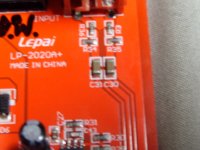
I have a Lepai - LP-2020A+ I bought from Parts Express on 9/3/2015 & want to replace the capacitors. The model is #30418B & I can't find anyone on the internet that has this new model. The model # is now placed on a sticker on the bottom of the chassis & not printed on the board itself like older models are. My problem is that C20 & C21 now use SMD Chip Capacitors & can't find out there values threw a schematic. I also don't know what C30 & C31 values are because the SMD Chip Capacitors are larger than previous board models, so they must have different values now. Numbers C30 & C31 are the capacitors on the input signal path circuit & are the most important mod to perform. I guess I could do without changing C20 & C21, but I need to change C30 & C31 to greatly reduce distortion at high volume & is a must do modification. I have found out that previous board models have a value of 2uf 63v or 2.2uf 63v or 3.3uf 63v for C30 & C31 & I don't have a clue what my board uses. What happens when you raise or lower capacitance of C30 & C31 of the signal input path circuit? Will I burn anything out on my board trying out different value capacitors in the input signal path circuit? I noticed that all the SMD Resistors on the input signal path circuit are all the same values for all newer board versions from 2013 & up. I need an expert here & can't get an straight answer from anyone I have asked for help from. Please can anyone help me out?
I have a Lepai - LP-2020A+ I bought from Parts Express on 9/3/2015 & want to replace the capacitors. The model is #30418B & I can't find anyone on the internet that has this new model. The model # is now placed on a sticker on the bottom of the chassis & not printed on the board itself like older models are. My problem is that C20 & C21 now use SMD Chip Capacitors & can't find out there values threw a schematic. I also don't know what C30 & C31 values are because the SMD Chip Capacitors are larger than previous board models, so they must have different values now. Numbers C30 & C31 are the capacitors on the input signal path circuit & are the most important mod to perform. I guess I could do without changing C20 & C21, but I need to change C30 & C31 to greatly reduce distortion at high volume & is a must do modification. I have found out that previous board models have a value of 2uf 63v or 2.2uf 63v or 3.3uf 63v for C30 & C31 & I don't have a clue what my board uses. What happens when you raise or lower capacitance of C30 & C31 of the signal input path circuit? Will I burn anything out on my board trying out different value capacitors in the input signal path circuit? I noticed that all the SMD Resistors on the input signal path circuit are all the same values for all newer board versions from 2013 & up. I need an expert here & can't get an straight answer from anyone I have asked for help from. Please can anyone help me out?
Attachments
- Status
- This old topic is closed. If you want to reopen this topic, contact a moderator using the "Report Post" button.
- Home
- Amplifiers
- Class D
- LP-2020A+ mod thread