Has anyone actually measured a tripath amp before/after modding?
I have a Muse MU15 (TA2024) and the performance is a far cry from claimed performance in tripath's datasheet. This is at 1watt into 8ohm... after lowering gain to ~3.6 to get rid of a horrible noise floor:
>1% THD... Perhaps performance gets better at higher output?
I can't see anything obviously wrong with their implementation and the build quality seems fine (Genuine Nichicon caps used).
Maybe the TA2024 just sucks... I've got a 2020A+ on the way because i'm curious
Last edited:
I have never seen before and after test results for either a TA2020 or TA2024 based amp. That's not to say it's not out there.
The general consensus is that the TA2020 sounds better than the TA2024. And a modded TA2020 is better yet.
While numbers shouldn't be ignored, the ultimate test is with your (hopefully unbiased) ears.
The general consensus is that the TA2020 sounds better than the TA2024. And a modded TA2020 is better yet.
While numbers shouldn't be ignored, the ultimate test is with your (hopefully unbiased) ears.
Got the Wimas and everything else in today. I see one problem already. Getting the Wima caps around that huge dual relay. The stock caps where angled out and have long leads where as the Wimas do not. Maybe pull the relay and just jumper it? But then, "pop" may be a problem.
TMM.... You may want to look at this blog concerning the TA2020 chip inside the Lepai.
Lepai LP-2020A+ | FF's electronics
Lepai LP-2020A+ | FF's electronics
Ermmm .. Could it be because these are Cheap imitation chips ?? I recently ordered a pair from 'Arjen' who claimed his were 100% Genuine.
A european 'dealing' thru Asia. His Claim of Genuine was the ONLY reason for buying from him.
My ***! is my printable answer to what was actually delivered. Ever seen a Genuine tripath chip with gold plated pins !? I haven't either.
Tripath has been 'gone' for Many years.. yet new chips keep appearing.
IMO ALL of Asia cheats.
It's OVER.. period. We'd best wake up and realize this.
Last edited:
Tripath the company has been gone for many years.Tripath has been 'gone' for Many years.. yet new chips keep appearing.
Tripath the class-D amp IC technology has not.
This was discussed briefly in another thread here not too long ago. You must've missed it.
Maybe there was a reasonable suggestion made that the same Taiwanese fab has produced these chips all along.
It wouldn't be the first time.

I finally got mine done. It seems like it sounds better but, it has been a week since I listened to it in it's stock form. Here are some pics....
Attachments
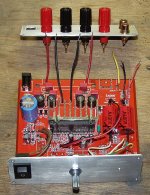
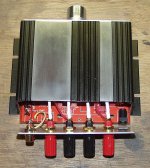
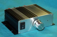
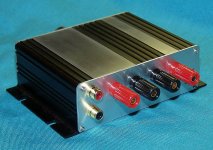
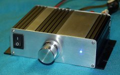
Thanks. I just couldn't stand all the lettering on the top. It was easier to do new end caps than to try and reuse the old ones only to have unused holes left.
I couldn't find any chemical to strip the lettering off the top so I had to bead blast it, and the anodize, off. I was going to leave it all black until I figured that out.
I couldn't find any chemical to strip the lettering off the top so I had to bead blast it, and the anodize, off. I was going to leave it all black until I figured that out.
OK I bought 2 PCB type 2020 amps for the car complete with film caps and no other gubbins. Tried on my garage speakers, fine, fit and forget. Car sounds really good now. I have a mixture of Morel and those banana mashins that I forgot the name of!
So I also bought a Lepai (+). It sounded better than the Goodmans amp/sub, so decided to mod it. Swapped the 4 signal caps out for film types and a bigger DC 4700uF.
BRILLIANT. The speakers are Morel 6 1/2" and 1" tweeters and have absolutely come alive. They are putting out more bass than the Goodmans Sub, so it needs to go.
Definitely recommended and taking the ceramic/electrolytic caps out is a must-do
Battery voltage can go "over" 16 volts after a really cold start (alternator cold) as a deliberate measure to "force" high current through the battery and help bring it to full charge. That high voltage situation last only a couple of minutes (but thats an eternity to electronics rated at less) and gradually falls back to a level determined by temperature. On a hot day with a hot engine the battery might only have around 13.2 volts across it when running.
You have to charge a battery at a higher voltage than resting voltage for it to charge. A 12V battery is about half dead at 12V. Charging voltage is normally 13.6V - 14.4V in a car. No, it won't hurt the battery. But it might hurt electronics expecting no more than 13.5V.
A switching regulator is ideal, because they typically don't care what the input voltage is. A linear regulator is fine too in this case, since if the battery voltage falls below the drop-out voltage, the regulator will just stop regulating.
A switching regulator is ideal, because they typically don't care what the input voltage is. A linear regulator is fine too in this case, since if the battery voltage falls below the drop-out voltage, the regulator will just stop regulating.
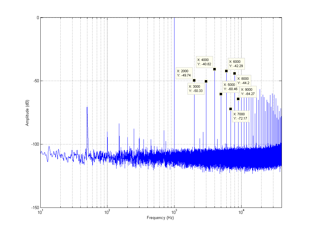
This thread needs less subjective opinions about capacitors and more objectivity, so i will add my 2c.
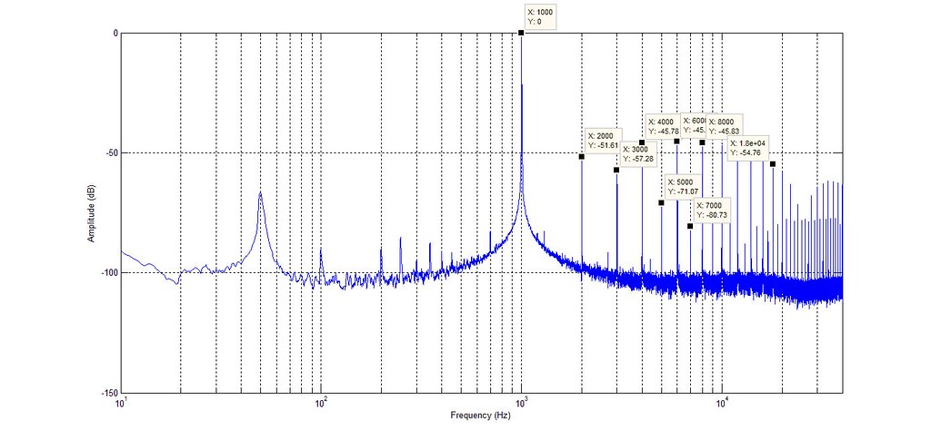
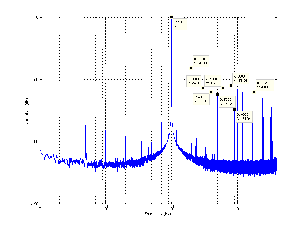
Measured my 2020A+, completely stock:
1W @ 8ohm, 1khz test tone:

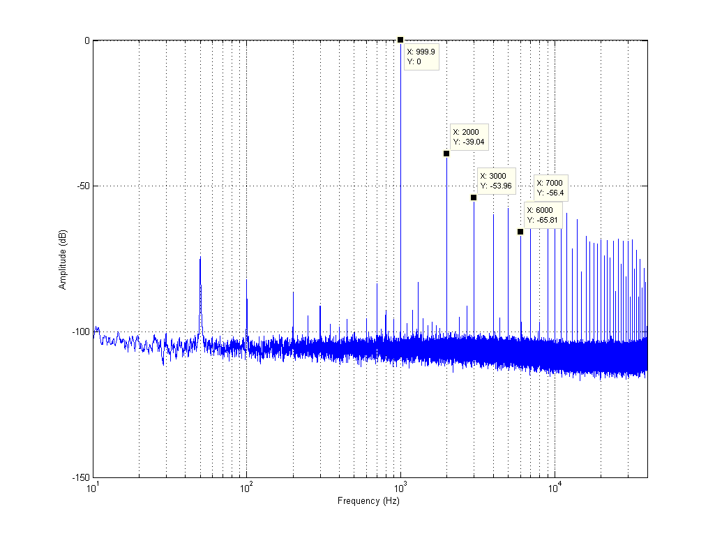
4.3W @ 8ohm (near max power):
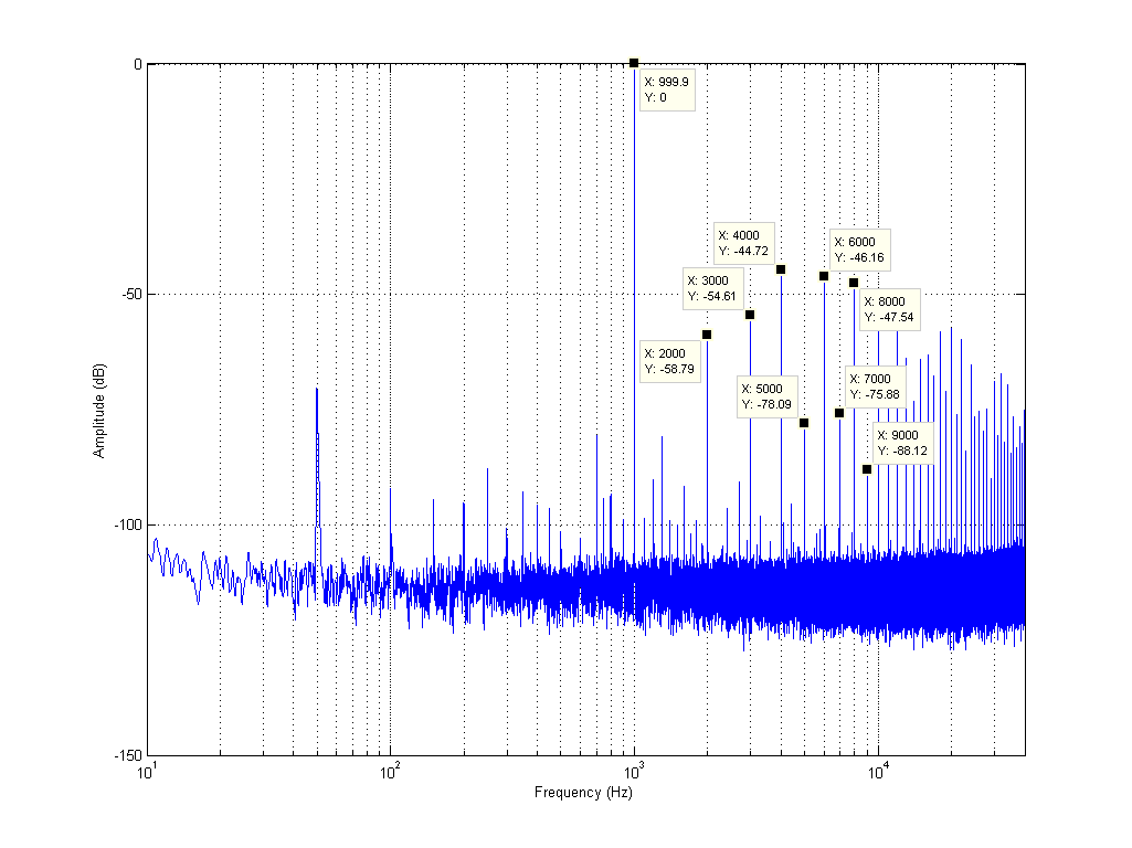
0.1W @ 8ohm:
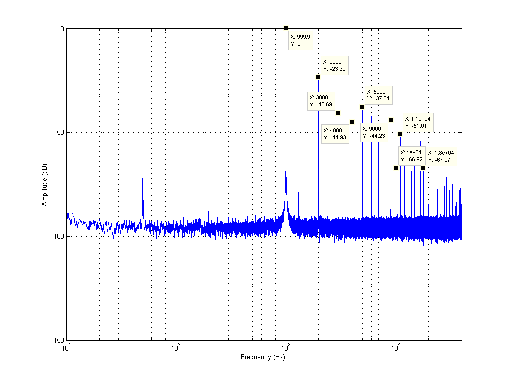
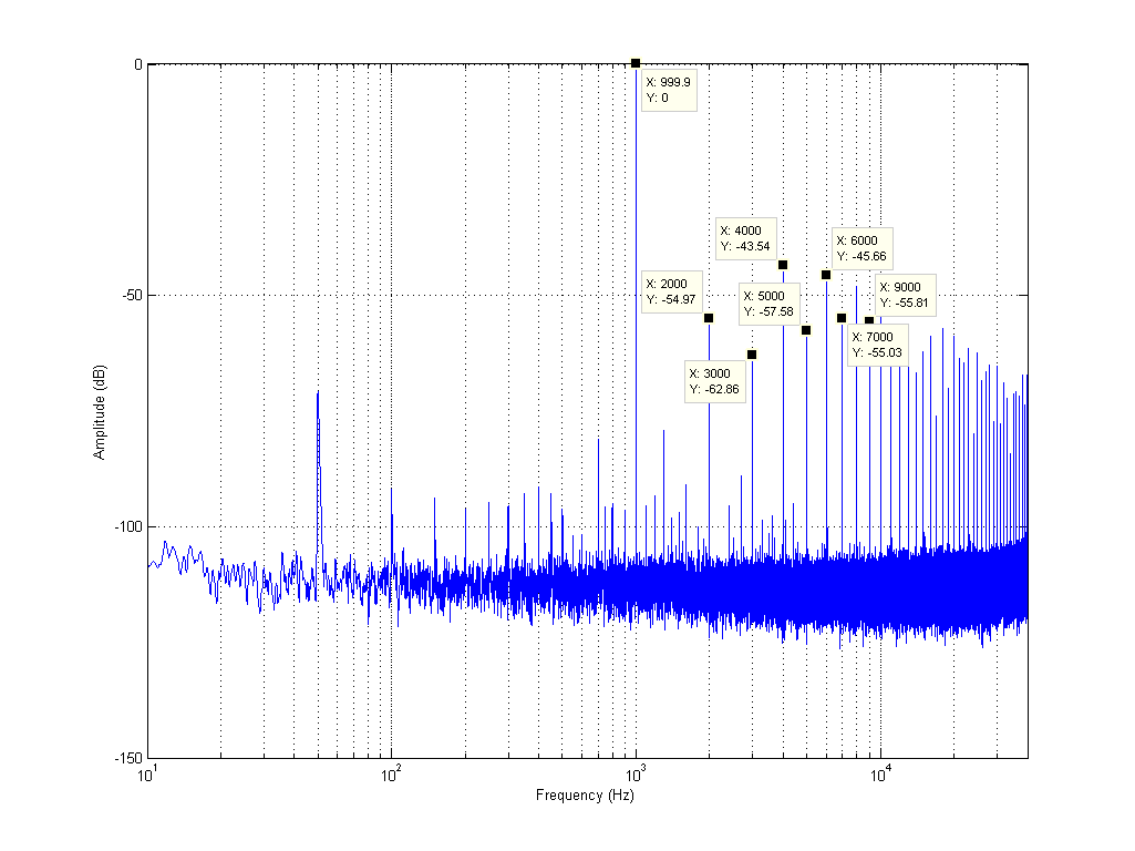
1W @ 4ohm (not sure what the hell is going on with the noise floor here!):
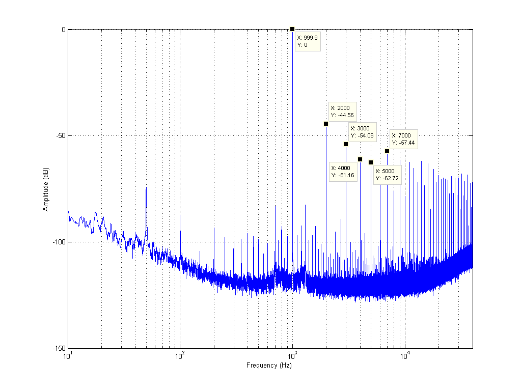
Oh dear, this is pretty awful distortion, especially at lower power levels (the most important ones!) and looks exactly the same as the Muse TA2024 amp i have. Distortion is okay i guess (except 2nd order) near max power, but since music is dynamic this is pretty moot. You can't play music at 4.3W without playing 0.1W simultaneously. It will however be much better playing loudly than quietly.
Anyone who has played with and measured speaker amplifiers and opamps will know that the level of distortion above is unlikely to be caused by the simple opamp circuits. Also the similarity to the Muse TA2024 amp (which has no preamp or tone control circuitry what so ever) immediately makes me suspect that the distortion is being produced entirely by the TA2020 chip.
Even at max power, i wasn't achieving anywhere near the quoted total harmonic distortion figure in the TA2020 datasheet which is 0.03% @ 10W 4ohm. 0.03% corresponds to -70dB, and i had single harmonics that measured higher than that! On 12v the best my chip can muster without clipping is 5Vrms @ 4ohm = (5^2)/4=6.25Watt and 6.3Vrms @ 8ohm = (6.3^2)/8=5Watt. My Muse TA2024 amp is similar. So we probably need a 13.5v supply to get rated power output, but you'd think it would still get close to the quoted 0.03% distortion.
I had a brainwave that maybe BOTH outputs need to be loaded up to achieve low distortion. So lets try that. Max power with both channels loaded with 4ohm resistors.
Nope. The general trend is that total harmonic distortion gets lower as power output increases - except 2nd order, which just gets worse as you crank up the juice (but also bad at very low power levels).
The first mod i tried was lowering the gain. Default value of Rf on my board is 22k, and Ri is 15k. According to the 2020 datasheet that gives us a gain of 12*(22/15)=17.6.
I soldered 20K resistors across pins 9 and 10, 12 and 13 of the 2020 chip. This lowers the gain to 12*(10.48/15)=8.4
Here are the results of that:
Odd order distortion goes down significantly, but even order seems to be relatively unchanged.
The next thing i tried was to replace the output inductors. I wound some 10uH aircores with 20AWG wire:
3rd order comes down, 5th, 7th and 9th go up! Why the heck did that happen? More on this later...
Then i tried some of the 'usual' mods in this thread. First i cut the trace between R18, R19 and the volume pot, therefore completely isolating the tone control circuit at both the input and output. I measured, and there was absolutely no change.
Then i removed one of the 2.2uf decoupling caps and connected my input signal directly to the input of the 2020 chip via a 560nF polypropylene cap. No change.
At this point i was getting frustrated as to why my measurements weren't repeatable. I'd go and change the gain resistor to another value, then change it back to 20k and get a worse result than when i first measured it with the 20k resistor.
Maybe heat is affecting it? First i sprayed the heatsink with freeze spray:
Then heated it up:

This may also go some ways as to explain why the distortion gets lower at higher power outputs.
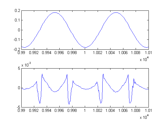
If we look at the waveform with the 1khz tone notched out, we can see that the distortion mechanism is completely changing with temperature (output signal on top, notched signal below):
Room temp:
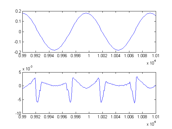
Cold:
Hot:
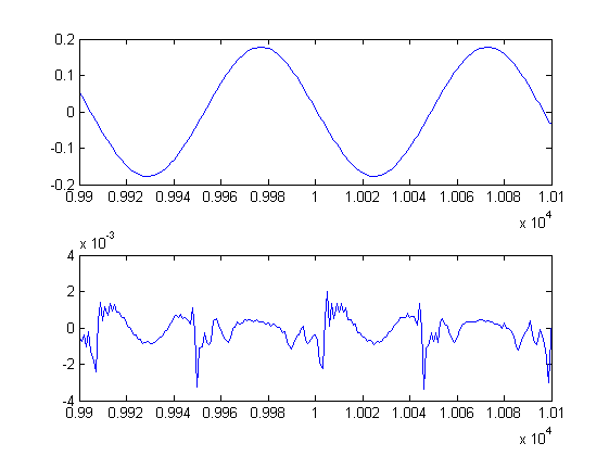
This in my eyes proves that the TA2020 chip itself is internally producing all of the distortion at the output and there is not much you can do to fix it. Reducing the gain is a worthwhile mod, but don't expect miracles. Running the chip hotter generally improves even-order distortion and running it cool improves odd-order. The happy medium seems to be the temperature it reaches at after running it at max power for several minutes (perhaps 45C?). Music won't let it get that hot (unless you severely clip the amp) so installing a smaller heatsink may actually improve performance in practice!
I haven't tested the amp with the tone controls enabled, but certainly there are no ill affects (at least amoungst the massive distortion caused by the 2020) in leaving it connected, plus it is generally nicer to have the knobs on the front of the unit actually do something (even if you never use them), rather than pointlessly disabling/removing them for no benefit.
I'm still yet to change any caps but having isolated all of them except the powersupply and output capacitors, and already using a decent regulated powersupply to power it, i'm going to predict that replacing the caps will be about as effective as pi**ing on a bushfire.
Measured my 2020A+, completely stock:
1W @ 8ohm, 1khz test tone:
4.3W @ 8ohm (near max power):
0.1W @ 8ohm:
1W @ 4ohm (not sure what the hell is going on with the noise floor here!):
Oh dear, this is pretty awful distortion, especially at lower power levels (the most important ones!) and looks exactly the same as the Muse TA2024 amp i have. Distortion is okay i guess (except 2nd order) near max power, but since music is dynamic this is pretty moot. You can't play music at 4.3W without playing 0.1W simultaneously. It will however be much better playing loudly than quietly.
Anyone who has played with and measured speaker amplifiers and opamps will know that the level of distortion above is unlikely to be caused by the simple opamp circuits. Also the similarity to the Muse TA2024 amp (which has no preamp or tone control circuitry what so ever) immediately makes me suspect that the distortion is being produced entirely by the TA2020 chip.
Even at max power, i wasn't achieving anywhere near the quoted total harmonic distortion figure in the TA2020 datasheet which is 0.03% @ 10W 4ohm. 0.03% corresponds to -70dB, and i had single harmonics that measured higher than that! On 12v the best my chip can muster without clipping is 5Vrms @ 4ohm = (5^2)/4=6.25Watt and 6.3Vrms @ 8ohm = (6.3^2)/8=5Watt. My Muse TA2024 amp is similar. So we probably need a 13.5v supply to get rated power output, but you'd think it would still get close to the quoted 0.03% distortion.
I had a brainwave that maybe BOTH outputs need to be loaded up to achieve low distortion. So lets try that. Max power with both channels loaded with 4ohm resistors.
Nope. The general trend is that total harmonic distortion gets lower as power output increases - except 2nd order, which just gets worse as you crank up the juice (but also bad at very low power levels).
The first mod i tried was lowering the gain. Default value of Rf on my board is 22k, and Ri is 15k. According to the 2020 datasheet that gives us a gain of 12*(22/15)=17.6.
I soldered 20K resistors across pins 9 and 10, 12 and 13 of the 2020 chip. This lowers the gain to 12*(10.48/15)=8.4
Here are the results of that:
Odd order distortion goes down significantly, but even order seems to be relatively unchanged.
The next thing i tried was to replace the output inductors. I wound some 10uH aircores with 20AWG wire:
3rd order comes down, 5th, 7th and 9th go up! Why the heck did that happen? More on this later...
Then i tried some of the 'usual' mods in this thread. First i cut the trace between R18, R19 and the volume pot, therefore completely isolating the tone control circuit at both the input and output. I measured, and there was absolutely no change.
Then i removed one of the 2.2uf decoupling caps and connected my input signal directly to the input of the 2020 chip via a 560nF polypropylene cap. No change.
At this point i was getting frustrated as to why my measurements weren't repeatable. I'd go and change the gain resistor to another value, then change it back to 20k and get a worse result than when i first measured it with the 20k resistor.
Maybe heat is affecting it? First i sprayed the heatsink with freeze spray:
Then heated it up:
This may also go some ways as to explain why the distortion gets lower at higher power outputs.
If we look at the waveform with the 1khz tone notched out, we can see that the distortion mechanism is completely changing with temperature (output signal on top, notched signal below):
Room temp:
Cold:
Hot:
This in my eyes proves that the TA2020 chip itself is internally producing all of the distortion at the output and there is not much you can do to fix it. Reducing the gain is a worthwhile mod, but don't expect miracles. Running the chip hotter generally improves even-order distortion and running it cool improves odd-order. The happy medium seems to be the temperature it reaches at after running it at max power for several minutes (perhaps 45C?). Music won't let it get that hot (unless you severely clip the amp) so installing a smaller heatsink may actually improve performance in practice!
I haven't tested the amp with the tone controls enabled, but certainly there are no ill affects (at least amoungst the massive distortion caused by the 2020) in leaving it connected, plus it is generally nicer to have the knobs on the front of the unit actually do something (even if you never use them), rather than pointlessly disabling/removing them for no benefit.
I'm still yet to change any caps but having isolated all of them except the powersupply and output capacitors, and already using a decent regulated powersupply to power it, i'm going to predict that replacing the caps will be about as effective as pi**ing on a bushfire.
Last edited:
- Status
- This old topic is closed. If you want to reopen this topic, contact a moderator using the "Report Post" button.
- Home
- Amplifiers
- Class D
- LP-2020A+ mod thread