I am getting a dc offset at the output of the amp of about 1 volt. I have a pair of cheap speakers that I am using to test and you can hear a small hum with no source connected which I am sure is due to the dc offset, but with the volume turned up it doesn't sound that bad. Either way I would like to lower the dc offset to an acceptable level, but I'm not really sure how. Should I raise the value of the resistor from the input of the 47k resistor to ground (currently 100k). Any more suggestions would be great. Thanks again.
Disconnect the input of the LM3875 from the tube stage. Then connect a resistor of low value like 10 K from + input of the Lm3875 to ground. Switch on the power and see if you get a voltage offset . If the voltage is a few mV , then the tube stage will be responsible for the offset. Note that the circuit you showed has no capacitor from 680 ohm to ground. That gives the LM3875 dc gain . So any dc offset at the input will be multiplied several fold.
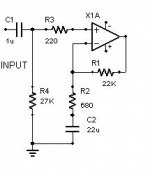
If you put in a capacitor between 680 ohm and ground , the offset should drop considerably . You can use any large capacitor to test or even just disconnect one end of the 680 ohm resistor. But for actual use the capacitor should be according to the application note or say about 22 to 100u F. A 35V or 50 V rating.
If you use an electrolytic ( most likely ) the plus should go to ground and -ve to the 680 ohm resistor.
Should I connect the capacitor in parallel with the 680 ohm resistor or in series to ground? As soon as I hear from you I am going to add this and see if the offset lowers.
I am almost positive it is the tube stage that is causing the DC offset because as soon as it is turned on it jumps to 33 which is the gain of the gainclone but then drops quickly down to 1 volt. So I am assuming the tube stage is the culprit, but I'm sure there are some tricks to lower this offset. Thanks for the help.
I am almost positive it is the tube stage that is causing the DC offset because as soon as it is turned on it jumps to 33 which is the gain of the gainclone but then drops quickly down to 1 volt. So I am assuming the tube stage is the culprit, but I'm sure there are some tricks to lower this offset. Thanks for the help.
The capacitor is connected in series with the 680 ohm resistor to ground. Positive going to ground and negative going to the 680 ohm resistor. See the attached diagram. Ignore other parts values as these may not b ewhat you used. Just look at the 680 ohms resistor and 22uF capacitor.
Cheers.
Cheers.
Attachments
I am going to add that cap here shortly and check again. Thanks for all your help. Any advice on a few standard perfvormance tests I can perform? i have access to a 4-channel digital ossciliscope, function generator, and many dmms's. Frequency response and total harmonic distortion would be the tops. I also see that with the tube buffer the output waveform has a softer clipping characteristic, while the chipamp itself has fairly sharp clipping. Thanks again.
For a start you can check frequency response of the tube stage with the chip amp connected. You can also check overall frequency response. At say 1 watt into 8 ohms. That's 2.83 volts rms at the output of the power amp. You can also check distortion at this level. Then you can do the same at say 10 watts ( 8.94 volts rms). Your load ( 8 ohm resistor ) will get pretty hot . You couldn't possibly test with a loudspeaker connected ! You will have to use at least a 20 watt resistor to prevent it from becoming excessively hot. Might burn your fingers just touching it on load!
Check for clipping limit . At this stage the tube amp output must be a clean looking sine wave. Your tube stage must never clip before or at the same time as the LM3875 stage .
Have fun. I'll be off to bed in 30 minutes or so !
Cheers.
Check for clipping limit . At this stage the tube amp output must be a clean looking sine wave. Your tube stage must never clip before or at the same time as the LM3875 stage .
Have fun. I'll be off to bed in 30 minutes or so !
Cheers.
About the clipping level. When the LM3875 starts to clip the tube stage output should still be clean. Under no condition must the tube section clip before the LM3875 stage. If it does , you will have to change the operating point of the tube.
Cheers and good morning ! I'm off to sleep .
")
Cheers and good morning ! I'm off to sleep .
I have a 10-ohm, 10 W resitor, 50-ohm 5 W resitor, and a 220-ohm 10 watt resitor. Can I parallel these 3 resitors and then wrap the thing with a lot of electrical tape and leave the two side wires open to i can connect to? That should be a wattage rating of 25 watts and a resistance of right around 8 ohms. Let me know if this might work.
Also, how would I measure the frequency response. Should I measure the rms output voltage for a few different input voltage levels and compare among a number of different frequency for each input? Then I could use that to calculate the gain for all of the different scenarios upon which I can use to create a graph from. any suggestions? Thanks.
Also, how would I measure the frequency response. Should I measure the rms output voltage for a few different input voltage levels and compare among a number of different frequency for each input? Then I could use that to calculate the gain for all of the different scenarios upon which I can use to create a graph from. any suggestions? Thanks.
After adding a 22uF electrolytic cap from ground to the 680-oh resistor, I have a DC offset of under 5 mV, which seems to be okay to me. There is still a very slight hum when the amp is connected to a loudspeaker, but you have to put your ear right up to the amp to actually here this. I don't know if this is from the tube stage or a combination of both stages, but it doesn't seem to be a huge problem right now.
I plotted the frequency response for the tube buffer, the LM3875 stage, and the amp as one unit. It seems to have a decent frequency response from 20Hz-20,000Hz.
Does anyone know a method to determine distortion at different power levels. I would like to do a few distortion tests to find out what effect the tube buffer has on the overall distortion of the amp. Thanks for the help.
Attachments
You could download the trial version of Spectralab or Spectraplus from the web and use that to test for distortion at different frequencies and levels. You need a decent sound card on your PC and and a 10K to 100K potentiometer on the input of the sound card to prevent overloading and damaging the sound card.
Alternatively you could use Audio Tester ( demo ) or RMAA ( free).
Google and you will find it. These are all audio frequency spectrum analysers ( FFT) which use your PC sound card.
The 10 watt resistor is still going to hog most of the power and so it will get very hot. Do not place the resistors on anything that might burn like wood. AND do NOT wrap the resistors in plastic or anything else. Let them be open and possibly near a fan so that they will get some extra cooling.
BE CAREFUL and you will have lots of fun!
Cheers.
- Status
- This old topic is closed. If you want to reopen this topic, contact a moderator using the "Report Post" button.
- Home
- Amplifiers
- Tubes / Valves
- Low Voltage Plate Follower 6DJ8 Buffer Power Supply