Amen.
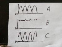
I guess you mean the bottom peaky part of a full-wave rectifier with no filter of any kind, like in A. But with capacitor input (B) or choke input (C) filters, there are no bottom spikes. Please note that voltage waveform at choke input (with choke of critical value) is a pure sinusoid - due to choke's reactance.Some noise is harder to filter than others. The 120 Hz “bizzzzzz” caused by P-N rectifiers working against trafo leakage reactance is among the hardest to eliminate. It’s and RF fundamental gated on and off at a 120Hz rate, making the nastiest kind of spectrum you can dream up.
Attachments
No, what you can get is a high frequency BURST right at the zero crossing, riding on the rectified and filtered DC. Ground inductances at those frequencies mean “ground is not ground” and it can get into everything. Snubbers on the diodes themselves can often minimize or eliminate it, but not always because the proper snubbing is load dependent. Audio loads vary hugely. If you are running a separate filament transformer it can usually be eliminated from that supply because it can be tuned for that load. On a shared core it can come and go depending on load conditions.
Yes, we are talking about the same thing, but in different words. Zero crossing for a SS diode is crossing the forward voltage threshold. Abrupt current cutoff, as well as abrupt turn-on at the forward voltage excites transformer ringing. Tubes and high current Ge diodes don't have this problem because their zero crossing is smooth.
Soft switching rectifiers are generally more lossy than their hard-switching counterparts - which may be tamed using lossy snubbers.
I would prefer the high-efficiency solution and focus an analogue designs with high immunity against any kind of external noise.
Following this path I prefer SS solutions with SMD parts.
I would prefer the high-efficiency solution and focus an analogue designs with high immunity against any kind of external noise.
Following this path I prefer SS solutions with SMD parts.

Not a transformer coupled inverter at all. Just a 50-ish % duty cycle square wave fed directly into an LC low pass. Just one hexfet, one schottky, an inductor and cap. It’s not actually rectified. Can be regulated with PWM. Single IC solutions exist from LT, just add LC filter and use a couple resistors to set output voltage. If the output current is relatively constant the inductor current can be made continuous - not switching off, but varying between a maximum and minimum. These things are relatively quiet as converters go. Everything else is noisier. Can be a LOT noisier.Since DC-DC converter also uses SS rectification of the output current, with synchronous rectifier followed by a step-down DC converter we arrive at the same problem that we started with.
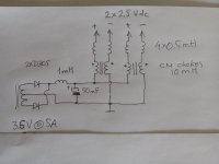
Here is a simple DC heater supply for a stereo 2A3 SET using D205 rectifiers. All inductors except CM chokes could be air core, same as used in speaker crossovers. Could be iron core as well to minimize stray fields, a few turns of thick wire on a small gapped core.
Transformer is 7.2 vct (3.6 x 2). I think better grounding would be at (-) outputs tied together.
Transformer is 7.2 vct (3.6 x 2). I think better grounding would be at (-) outputs tied together.
Attachments
Last edited:
This is worth reading. A simple snubber makes quite a difference. https://www.diyaudio.com/community/...rmer-snubber-using-quasimodo-test-jig.243100/
This is another interesting alternative. https://www.ti.com/lit/ds/symlink/lm74670-q1.pdf?ts=1710288245702
I decided to go with a Saligny active rectifier followed by two TDK i3AW step down buck converter modules for the GM-17 heater which needs about 7.5A at 6.3V nominal. One Saligny can feed two i3AW's for 2-channel. The i3AW output has a bit of hf ripple, I need to see how I need to handle that. If it is needed.
Jan
Jan
Attachments
sser2, you have decided to use a choke input filter, which many do not appreciate inherently imposes a very fast di/dt on the commutation event. That was not a serious issue with vintage HV supplies due to valve diode characteristics of soft approach to zero current, and no reverse recovery. However with ss diodes I'd suggest it is the inherent high dI/dt and reverse recovery that is your bane. I recall that Mark's paper in post #15 imposes higher than 'normal' dI/dt from the test rig, so is likely more to your application of choke input filtering, although not directly to your point about soft approach to zero current.
I note that you may be able to discern two commutation related artifacts if you were to probe the general noise environment - one relates to the bell ringing of the PT secondary leakage inductance and shunt capacitance, and the other to the reverse recovery characteristic of the diode due to snap back. The bell ringing for a typical capacitor input filter scenario is more a result of the diode snap response (as the dI/dt is quite benign from the slow dV/dt of a mains waveform), but I think there is an additional cause in your situation due to the choke input commutation process (which may have some influence from soft-approach down to zero current).
Commutation noise from a choke-input filter can be managed by deploying a small capacitor before the choke, as it can divert much of the higher frequency current loop close to the rectifier and PT secondary winding, and hence suppressing higher frequency noise current from egressing into the choke and beyond. The part value of such a capacitor would normally be low enough not to noticeably raise the output dc voltage (unless that was an aim), and its location (as to with the diodes) should preferably be at the secondary winding taps. The small capacitor also likely slows the commutation dV/dt of the diode's node.
Last edited:
Maybe I should be more forthcoming with my choice on this.
The Saligny means I have minimal losses in the rectifier, which would be appreciably with a total load current of 15A or so.
The use of the i3AW step down controller means I can use any transformer voltage (within reason) and still get exact 6.3V heater, with no change from mains variations. The output ripple is way above the audio band and there is zero chance of hum introduction in the cathode/heater circuit.
So there.
Jan
High Frequency current through a very small capacitance causes a high frequency wide-spectrum ground loop.
Capacitor transient currents have a very fast rise time. The fast rise time makes the transient current higher, even with a small capacitance.
Example, Gaussian bandwidth: 0.35/rise time. A rise time of 20us has a bandwidth all the way to 17.5kHz.
That is higher than my ear can hear.
But a slower rise time of 200us will put the bandwidth at 1.75kHz. Some of that rectifier hash is right in the most sensitive frequency range of our hearing.
Fix one problem, and create another problem to be solved.
- Home
- Amplifiers
- Tubes / Valves
- Low voltage high current rectification