Although there could be strong opinions about tube vs. solid state rectification, tubes objectively have no forward voltage cutoff, which causes ringing in the resonant tank of power transformer's leakage inductance and distributed capacitance. The ringing can be snubbed with an RC snubber, but the first few oscillations will still remain. Moreover, hard cutoff of SS rectifiers at forward voltage (about 0.7 V for regular Si diodes and 0.3-0.4 V for Schottky diodes) creates broad spectrum high frequency noise that is better be avoided.
The problem is especially important with low voltages such as those needed to power DC filaments of such tubes as 26, 45, 2A3, etc. With silicon diodes, the cutoff voltage may be as high as 30-50% of the rectifier output. And it goes without saying that noise is the last thing one would want in a filament supply.
I believe I found the solution to this problem: germanium rectifiers. These have forward voltages of 0.3-0.35 V, but that's not their main advantage. Importantly, their behavior in the low voltage-low current area is similar to that of tube rectifiers. They don't have the hard forward voltage cutoff. Here is a low voltage static plot for the Russian D305 Ge rectifier that I experimentally derived. D305 is a 10 A 50 V diode.
Attachments
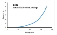

That would make sense if there were data for lower and higher decades, 0.1-1 mA and 100-1000 mA. The value of such data would be purely academic though as 350 mV is forward voltage and 2 mA is data sheet reverse current (which is basically leakage through equivalent parasitic parallel resistance).
Indeed. I just ordered a couple of Universal Saligny's from member Tiberiu for exactly this purpose!
Jan
Jan
Yes, they made quite a progress with these in terms of their current capability and price. The only problem that I see is that they cannot work in a choke input supply.How about synchronous rectification? No voltage drop.
You would hang a C at the output of the active rectifier. I don't see why that could not be followed by an L.
If you still need one, or maybe for nostalgic reasons.
Ask @iTiberius.
Jan
If you still need one, or maybe for nostalgic reasons.
Ask @iTiberius.
Jan
With all kinds of rectifiers including the synchronous. The first cap is charged with current pulses on the crests of AC voltage, and current cuts off when instantaneous AC voltage drops below capacitor voltage.
Yet another issue with synchronous rectifiers is that they require a minimum AC input voltage of about 4 VAC. This results in minimum of 5 VDC output. Have to throw away half of the voltage if it is to power a 2A3 filament.
Yet another issue with synchronous rectifiers is that they require a minimum AC input voltage of about 4 VAC. This results in minimum of 5 VDC output. Have to throw away half of the voltage if it is to power a 2A3 filament.
I have tested the reverse-recovery profile of a 1N92 Thomson (the Ge alter-ego of a 1N4003):Importantly, their behavior in the low voltage-low current area is similar to that of tube rectifiers. They don't have the hard forward voltage cutoff.
This is how it looks:
The p-p applied voltage is 10V, and with the 10ohm sensing resistor + the 50ohm of the generator, it results in a 80mA peak, both forward and reverse.
The trr is in the region of 3µs, and the recovery profile is relatively gentle and soft.
Nothing out of the ordinary, and you could find many standard silicon rectifiers behaving similarly... nothing to write home about...
OK, yes I see. In your case it's not a good solution.With all kinds of rectifiers including the synchronous. The first cap is charged with current pulses on the crests of AC voltage, and current cuts off when instantaneous AC voltage drops below capacitor voltage.
Yet another issue with synchronous rectifiers is that they require a minimum AC input voltage of about 4 VAC. This results in minimum of 5 VDC output. Have to throw away half of the voltage if it is to power a 2A3 filament.
Bummer.
Jan
Ge diodes are not all the same. Small signal diodes, such as Russian D2 or D9 series are fast and have cutoff characteristics similar to those of Si diodes, the only difference a knee at lower forward voltage. The 10 A D305 is very slow by all standards, and it has smooth transition. 1N92 is in the middle between them, that's what I saw with equivalent Russian D7 series diodes.
Use the synchronous and Buck convert the higher DC down. Slow your rise/fall times and filter the hell out of it - at least the fundamental can be up in the 100khz+ range not 120 Hz. Freewheeling diode can be a schottky. Buck converters are quieter than other types naturally, so it may not be too bad.
This is an option, but it would have to involve a lot if screening and filtering. Capacitor input filter noise, DC-DC converter carrier frequency noise. I believe it is better not to create noise in the first place.Use the synchronous and Buck convert the higher DC down. Slow your rise/fall times and filter the hell out of it - at least the fundamental can be up in the 100khz+ range not 120 Hz. Freewheeling diode can be a schottky. Buck converters are quieter than other types naturally, so it may not be too bad.
There is some but with low RDss on MOSFETs, it can be pretty tiny. If I recall, Linear Technology makes a driver IC that works with 4 MOSFETs connected in bridge configuration to implement that functionality.How about synchronous rectification? No voltage drop.
Some noise is harder to filter than others. The 120 Hz “bizzzzzz” caused by P-N rectifiers working against trafo leakage reactance is among the hardest to eliminate. It’s and RF fundamental gated on and off at a 120Hz rate, making the nastiest kind of spectrum you can dream up.This is an option, but it would have to involve a lot if screening and filtering. Capacitor input filter noise, DC-DC converter carrier frequency noise. I believe it is better not to create noise in the first place.
Some of the MOSFETs are actually better than mechanical switches for ON resistance. I'm surprised at how good the transistors are in that regard And, they don't wear out!It's in the single-digit mV range.
Jan
- Home
- Amplifiers
- Tubes / Valves
- Low voltage high current rectification