PSU
Hi,
The Dutch approach,you know....
It doesn't mean you have to do it this way.
As for the heater supplies,I'd rather feed the 6AS7G 2.5A + AC from a dedicated xformer and use another xfromer to feed the 6DJ8 from a DC regulated supply.
Don't worry about the seemingly low 150 VDC B+ voltage,both tubes were designed to operate at low B+.
If you want to use this circuit as a line stage as well a nice regulated PSU would certainly pay off.
Cheers,
Hi,
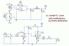
And in the notes about this amp, it says C1, C2, R5 is shared between both channels.
The Dutch approach,you know....
It doesn't mean you have to do it this way.
As for the heater supplies,I'd rather feed the 6AS7G 2.5A + AC from a dedicated xformer and use another xfromer to feed the 6DJ8 from a DC regulated supply.
Don't worry about the seemingly low 150 VDC B+ voltage,both tubes were designed to operate at low B+.
If you want to use this circuit as a line stage as well a nice regulated PSU would certainly pay off.
Cheers,
trespasser_guy said:I, too, thought it was a bit low...
150V is in the right range for a 6AS7. I didn't realize that was the tube you were using.
And in the notes about this amp, it says C1, C2, R5 is shared between both channels.
Yes. What's wrong with that?
It is nice to know I can use higher amp ratings... I found many transformers that could have been used that I ruled out because the A was wrong...
You will never find the exact specs you're looking for on any given project! Designing a power supply is a lot of educated guesses.
Doesn't the heater supply need to be regulated?
Why? You're using AC on these, right? so keep it simple.
quote:
--------------------------------------------------------------------------------
And in the notes about this amp, it says C1, C2, R5 is shared between both channels.
--------------------------------------------------------------------------------
Yes. What's wrong with that?
Nothing... just was pointing that out since it was in a special instruction area. I liek it better that way- I don't have to buy as many expensive caps (they are around 4-ish $... which is a lot when I am trying my darndest to keep it at or under $100...)
I thought that if it put out more A then it would damage the tubes because of the excess current... nice to know it doesn't.
If you have a 300-0-300 transformer going through a rectifier, you actually have 600V, right? Just wanted to know- not toally relevent to anything...
And I did intend to use AC heaters... Can the E88CC use AC heaters?
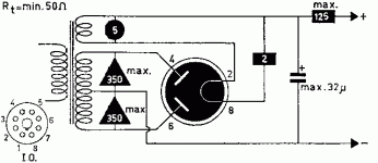
Also, a question I have about the rectifier... Which pins do I connect to what? Your scems don't have the pin layout-- I think I could guess, but I don't wanna blow anything up unecessarily...
5Y3GT
Hi,
No problem.
See pic:
Cheers,
Hi,
And I did intend to use AC heaters... Can the E88CC use AC heaters?
No problem.
Which pins do I connect to what?
See pic:
Cheers,
Attachments
I have been using the online TDSL thing... it has helped me a lot, and oddly enough, the guesses I made about pins were correct based on the pic you just posted.
I am intending to try out this tube design to see if I can actually do it... it seems really easy, but for some unknown reason, it may just not work. This would be bad, but I would lose a minimum amount of money. If it works, then I will continue research about tubes and get needed books.
EDIT: How will I hook up the heater supply? The tubes use pins 4+5 for heater supply and 9 for ground on the E88CC, and pin something else for ground on the 6AS7G. I am not at home with my stuff, so I am not sure here... but do I just run a wire from the supply to pin 4, then from 4 to 5? Would this work?
t_g,
Joel is right: get a manual.
In the mean time, download a copyof TDSL from Duncan amps website.
I just derived the following with reference to TDSL:
Heater wiring:
From the transformer, run a twisted pair of wires to the nearest valve, then daisy chain to the next.
The E88CC should have one wire to pin 4, and the other to pin 5.
Pin 9 (shield) should be grounded.
The 6AS7 should have one wire to pin 7, and the other to pin 8.
There is no pin to be grounded.
Cheers,
Hi,
Is there any other reason?
Cheers,
It's true that one should mount the small signal stage farthest from the transformer.It is probably wise to wire the 6AS7G first and than daisy chain to the ECC88.
Is there any other reason?
Cheers,
HEATERS.
Hi,
The 6AS7G will carry 2.5A of heater current and hence will require much thicker wire gauge.
If this is wired up first the daisy chain to the ECC88 can use as thin a gauge as required.
In this way chances for hum pick up by other components is reduced.
If we were to wire the ECC88 first, the amount of current going through it would more likely induce hum and you would require a wire thickness that would hardly fit the noval socket connecting points.
Cheers,
Hi,
Is there any other reason?
The 6AS7G will carry 2.5A of heater current and hence will require much thicker wire gauge.
If this is wired up first the daisy chain to the ECC88 can use as thin a gauge as required.
In this way chances for hum pick up by other components is reduced.
If we were to wire the ECC88 first, the amount of current going through it would more likely induce hum and you would require a wire thickness that would hardly fit the noval socket connecting points.
Cheers,
In addition to what guage... single strand or multi-strand?
I have a HUGE supply of 22 guage single... and might be able to salvage some 16-18 guage multi-strand... but am not sure.
What would be best? I will probably be using the leads of the resistors/caps mostly, but will need wire for the longer runs.
I have a HUGE supply of 22 guage single... and might be able to salvage some 16-18 guage multi-strand... but am not sure.
What would be best? I will probably be using the leads of the resistors/caps mostly, but will need wire for the longer runs.
WIRES
Hi,
Here's a link to a conversion table:
AMPLEPOWER
While it was set up for different reasons,it will still give you some idea.
If I come across a better one I'll post it.
The idea is not to overdo it when it comes to heater wires,the less metal the smaller the chance for it to pick up rubbish and hum.
Also it will have a smaller stray field then thicker gauges.
As to whether to use solid strand or multi strand wire,it won't make a difference on the sound (?) when used for the heaters, but I find solid strand wire a lot more convenient to work with.
Another advantage is that when you push the heater wires against the chassis it will quite likely stay there,whereas multistrand will try to regain its' previous position.
Cheers,
- Status
- This old topic is closed. If you want to reopen this topic, contact a moderator using the "Report Post" button.
- Home
- Amplifiers
- Tubes / Valves
- Low power tube amp for headphones

