It depends how close you still call it matched .. I would say form a batch of 100 2SK170BL' s, twenty are matched close enough. For such a single ended configuration, close matching is not that imported .. compared to a LTP configuration. Source resistors ( up to 33Ohm won't hurt that much) will help a bit.. but since I'm aiming for a low noise amp, I try to avoid that.
grzz,
Thijs
grzz,
Thijs
tschrama said:I did think about it, and it would be super cooolll..... prices at farnellinone are about 50 Euro for each peltier element, but that is without power supply .... right now I'm just checking various publications and datasheet, i'll first make a SPICE design before I built anything. .. so I need SPICE model parameters.. I allready have the 2SK152 on order, I got about twenty 2Sk170 matched, and several alternatives on order or on sample request.
My very first objective will be to measure a MC-phono step-up amplifier, maybe by using the first stage of the N. Pass Pearl-phono stage...
Eventhough, for once, my financial situation is not llimiting a project, time and space (just moved to life togheter with my girl-friend) is .. My house is a mess, packed moving-boxes allaround, and my hobby-desk is dismanteled in parts
Peltiers at farnell are expensive. check if you can find Kryotherm distributor somewhere. Or some other russian/chinese. I paid 17 euros for 50w peltiers here(computer overclocking shop) For serious use buy liquid nitrogen, its not that expensive
(alltough there is not any quarantee that your semiconductors are less noisy with LN temperatures, they might refuse to work as well)
jackinnj said:Erno Borberly has a couple of articles in this June's AudioXpress which implement a "paired" complementary JFET amplifier --
and by the way -- I modeled the SQUID ULN preamplifier and it would appear that it should oscillate around 10 MHz.
Complimentary is the efficient way to go. If the circuit is going to use a gob of current might as well put it through complimentary devices that otherwise would be only current sources.
And as far as input C, I'm assuming that parallel JFETs are to be driven by a very low impendance souce.
Thanks Jackini, will try it myself too.
I was thinking the same, but you need an extra power supply for complentary: only a V+ won't do, you also need a V- ... ..
Most of the time the Zsource will be less then 750, being the output of the distortion analyzer , but it needs to be a bit general purpuse too...
Complimentary is the efficient way to go. If the circuit is going to use a gob of current might as well put it through complimentary devices that otherwise would be only current sources.
I was thinking the same, but you need an extra power supply for complentary: only a V+ won't do, you also need a V- ... ..
Most of the time the Zsource will be less then 750, being the output of the distortion analyzer , but it needs to be a bit general purpuse too...
Mine is on back-order for over a month now..... they are becoming hard to find, allthough some on-line book shops claim the have a few in stock... If Audioexxpress is really going to reprint it.. I'm both very happy, and slightly afraid of having waisted my money on my current back-order...
Anybody checked out the lovoltech-Jfets ? They have forward transconductance in excess of 10 A/Volt, and should have lowest noise voltage of all transistors, though practically, the noise voltage lower limit would be the gate resistance of 0.5 Ohms.
http://www.lovoltech.com
best regards,
Hartmut
http://www.lovoltech.com
best regards,
Hartmut
Well today I finally finished the low-noise design I settled for. Got my first measurements right away :
 0.26nV/sqrt(Hz)
The circuit came out to be surprisingly simple.. al fits easely on 3x4 cm prototype board, supplied by 6 x 1.5V batteries, drawing 30mA of current, through 4x 2SK369, 220//220 Ohm I-to-V giving 27dB gain to a LT1037 opamp, @ 100 -to-47K feedback giving a total of about 80dB gain. Bandwidth (10R source) is 330Hz to 82KHz, noise is about 0,86mV rms (input shorted right at the JFETs gates. The thermodynamic noise of 50cm of coax is easely detected.
Things turned out to be much easier than I hoped for.. shielding the amplifier didn't actually improve much, a faraday-lab wasn't needed at all. I wonder why this has never been used for a ultra clean MC phono amp
Thanks all you guys for the tips... Next thing is the utra-pure oscilator... maybe tommorow...
Best regards,
Thijs
0.26nV/sqrt(Hz) The circuit came out to be surprisingly simple.. al fits easely on 3x4 cm prototype board, supplied by 6 x 1.5V batteries, drawing 30mA of current, through 4x 2SK369, 220//220 Ohm I-to-V giving 27dB gain to a LT1037 opamp, @ 100 -to-47K feedback giving a total of about 80dB gain. Bandwidth (10R source) is 330Hz to 82KHz, noise is about 0,86mV rms (input shorted right at the JFETs gates. The thermodynamic noise of 50cm of coax is easely detected.
Things turned out to be much easier than I hoped for.. shielding the amplifier didn't actually improve much, a faraday-lab wasn't needed at all. I wonder why this has never been used for a ultra clean MC phono amp
Thanks all you guys for the tips... Next thing is the utra-pure oscilator... maybe tommorow...
Best regards,
Thijs
sorry, no circuit yet.. but the description should be enough I thougth, surely for the seriously interested peolple. Since I'm still dreaming of a publication somewhere ... I keep the circuit to myself for now.. but it's really simple, nothing fancy.. The NP pearl is very similar.
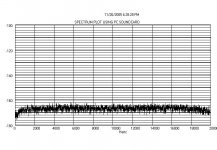
So toaday I started measuring the input sensitivity of my PC onboard soundcard. Using the Line-in with the volume all the way down; it is 1,00Vrms preciesly at 2KHz. The Dazyweb spectrum analyzer gives me -23dB at that setting, so I adjusted the offset to 23dB.
Then I substracted 80dB to correct for the gain of my amplifier: offset becomes -57dB..
I get around -166dB to -168dB
So that'll be the limit for this set-up on the measurement side.
Next thing is the ultra low noise , low THD oscilator.
Cya all.
opps, allmost forgot the spectrum picture
PS
Bandwidth is 600Hz to 140KHz, made a small error yesterday, due to the bandwidth settings of the HP Vrms meter.
So toaday I started measuring the input sensitivity of my PC onboard soundcard. Using the Line-in with the volume all the way down; it is 1,00Vrms preciesly at 2KHz. The Dazyweb spectrum analyzer gives me -23dB at that setting, so I adjusted the offset to 23dB.
Then I substracted 80dB to correct for the gain of my amplifier: offset becomes -57dB..
I get around -166dB to -168dB So that'll be the limit for this set-up on the measurement side.
Next thing is the ultra low noise , low THD oscilator.
Cya all.
opps, allmost forgot the spectrum picture
PS
Bandwidth is 600Hz to 140KHz, made a small error yesterday, due to the bandwidth settings of the HP Vrms meter.
Attachments
So, I guess you all noticed that -168dB isn't even close to 0.26nV/rtHz ... clearly something must be wrong.. Well it seems that the DazyWeb spectrometer isn't able to to the offset calculating corretly, and the number of point to do the FFT on is fixed...
So I build my onw in LabVIEW.... now I can adjust the amount of FFT samples (44100), gain of the pre amp (10K) ... I got 0.375nV/rtHz, which is much better but still significanly higher than I measure on my HP Vrms meter. Maybe the excess bandwidth is bugging me?
Still, 0.375nV/rtHz equals -188.5dB rel. 1Volt noise floor.. , which low enough I think.
grzz,
Thijs
So I build my onw in LabVIEW.... now I can adjust the amount of FFT samples (44100), gain of the pre amp (10K) ... I got 0.375nV/rtHz, which is much better but still significanly higher than I measure on my HP Vrms meter. Maybe the excess bandwidth is bugging me?
Still,
0.375nV/rtHz equals -188.5dB rel. 1Volt noise floor.. , which low enough I think. grzz,
Thijs
Some new results:
I connect the notch filter. It is based on 1K5 resistors, which wil ultimately limit the resolution to just above a 1nV/rtHz.. still this should equal -180dB rel. 1Volt.. But the notch filter is still only passive, no attempts have been made yet to higher the Q of the filter, so expect 2Harmonic to been down at -12dB and 3rdH down to -6dB (?) ..
Then I connected the trusty HP oscilator which I know has about -74dB 2ndH and 3rdH .. due to the simplicity of the notch filter I cann't put more than 20mV at the input.. this will all be bettered at a later stage. I allready have achieved 100dB attenuation for my previous notch filter, this one is going to be better!
On the picture you clearly see that the Fundamental of 1KHz is attenuated by the notch filter by about 60dB.. You see the harmopnics and the noise floor somehwhere around 3nV/rtHz.. (-170dB) about the figure I was aiming for...My CRT monitor clearly interferes , so I switch it off for e few seconds.
The THD of the HP oscilator checks out at around -74dB
Attachments
- Status
- This old topic is closed. If you want to reopen this topic, contact a moderator using the "Report Post" button.
- Home
- Amplifiers
- Solid State
- low noise JFET, how about this one