Nico Ras said:
Pure physics.
This really explains it.
I guess a degree in conventional physics is no use.
analog_sa said:
This really explains it.
I guess a degree in conventional physics is no use.
What are you trying to tell us. That you have a degree in conventional physics?
You commented: "A remarkably strong claim. Would you care to explain?"
I don't understand your question, what is so remarkable about the claim?
HKC said:Hi Nico
I am planning to build a pre-amp for my Pass A40 power amp. Your design impressed me. Before I can go ahead to proceed with this pre-amp. I like to know what is the value of R1 & C2 (220P same as C3 I guess) on the line stage?
Dear HKC,
Please indicate what rail voltage do you intend to operate on. I will adjust the values so that the quescient current is optimised for your supply.
I have done two versions of the pre-amp, one consisting of several long tail pairs in parallel with the aim that non-coherent noise would add reducing the total noise by SQRT(5).
I have also made some improvements by inserting a constant current generator in the tail of the differential pair which improved THD 20 quite significantly. I have also added a simple output offset adjustment that can be set to as low as a few microvolt.
Please match the transistors as this improves the symetry of the stimulus considerably.
If you would like the Gerber files to have PCBs done I shall gladly e-mail them to you.
As you can see, the pre-amp is quite capable to swing very close to the rail voltages and it would take quite a large signal to drive it into gain compression. The higher your supply the greater the linear area of operation.
The current offering uses BD139_16/BD140_16 and suited to ±40V rails. I propose transistors with higher Vce if you intend to run it at higher rail voltages such as the MJE15030/1
The base collector feedback capacitors are only to supress any high order spurea and 82pF is quite suffiecient. The GBP of the amplifier remains at about 2 MHz and the slew rate is measured to be 80V/uS well matched transistors are used.
Also if you need it for vynil then an RIAA equalisation network in the feed-back loop will be necessary. It can be switched in and out of circuit when using CDs and a flat lower gain can be selected.
The output impedance of the pre-amp is low enough to drive 32 Ohm headhones very well.
Although I use a simple diode bridge and two 4700uF caps per rail, I have had better results from a capacitance multiplier on each rail. Since it is a class A amp, it draws virtually a constant current and that makes a capacitance multiplier a good choice.
If you want to add a current source in each tail of the differential amplifier, I found that 1.13 mA provides for the lowest THD measured at about 0.61m%. There is only one measurable harmonic at twice the fundamental frequency and higher order harmonics lie below the noisefloor of our HP spectrum analyser at 10 Hz RBW.
Two tone intermodulation products (at an output of 10V p-p) are only bearly visible above the noise floor at frequencies space by less than 1 kHz.
If there is anything at all I can do to help, I will be a pleasure.
The circuit topology is that of full complementary sysmetry class A amplifier and what goes for the lower half applies to the top half. The components are identical for each mirror image.
Kindest regards
Nico
Hi Nico
Thank you for your reply.
I like to have +/- 50V rail for the pre-amp.
I will be happy if you can send me the Gerber file of the PCB layout then I can send the file for PCB fabrication.
I have check with local parts vendor and realize MJ15030 & MJ15031 are available so I will go for these transistors.
I also need the PCB layout for the RIAA stage. Please send it to me.
Instead of using a simple diode bridge regular would it be any problem if I use shunt regular for this pre-amp because I already have it well prepared for any of my new pre-amp project.
Once again thank you for sharing & sending information of this pre-amp to me.
Samuel Jayaraj said:Nico what about MJE/KSE 340 and 350 for high voltage applications?
Hi Sam,
I am cannot really comment on which transistors to use, I believe that if you have heard these transistors and are happy that they could sound good then there is no harm in using them.
What I have used is simply what I had and used for years. It is like your brand of beer. All beers probably tases awful but we have developed a taste for a single brand and swear that it is the best tatsing beer available and everyone else drinks junk.
To be on the safe side transistors should have a Vce equal to both rails, plus a bit. Always do a worst case analysis for all the components to see if they will handle what is expected of them over eternity.
Then build it, listen and tweak if you have to. It is hard to tell what to tweak but every diy guy/girl suspects something could be better, it usually is not but the results are sometimes different with each tweak not necesarily better or worse, just different.
Do not always believe what anyone says, try it and see what you think, if it is better for you then adopt it, else reject it and stick with what you like.
In commericial audio there is always the claimed best, same as cars, wine, toothbrushes and everything else. In DIY yours is always the best until you find something more apealing and you will adopt this as your own and it becomes your new reference of what is best (for you).
I have been designing audio circuits for myself and others with simular tatstes for more than 40 years, there are no golden rules or best ways, every designers rules are golden and his ways are the best!
You cannot gain experience from reading, cutting or pasting you will only learn from trying what is mythical and what is real to you.
Kind regards
Nico
Nordic said:Nico, kan ek daai Gerbers kry?, wag, werk dit in eagle? of wat sal ek moet gebruik?
Dear Nordic/HKC,
for the benefit of those non Afrikaans speaking members I reply:
Gerber file format is a standard for Gerber photo plotters. It is a coordinate plotter command file, simular to HPGL.
Most PCB design software has Gerber import facilities, so it is possible to import the Gerber file format into some PCB editors.
Although most PCB editors generate files with the extension .PCB none of them are compatible with each other making PCB file interchaging impossible.
The problem with Gerbers and DFX formats is that you are importing bitmaps and the flexibility to edit the design is not as practical as it may seem.
This is mainly due to the fact that there is no component library to reference and it will just remain a set of graphics in different drawing layers, making it difficult to manipulate.
My PCB layout is probably no better than the next person, but using a layout that already works saves a lot of time and trouble.
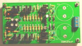
What I would like to do is to remove the diode bridge and large capacitors of the board, this saves real estate and would make the PCB cheaper as the two capacitors occupy almost 1/3 of the board.
This would make it more flexible to use your own power supply and requirements.
I will complete the Gerbers and post it tomorrow for those who whant to make PCBs and a PDF file with the plots so one can see the physical layout pictorially. I will also include a parts list and some resistor changes necesary for different operating voltages.
If this is acceptable, it will be only a pleasure.
Kindet regards
Nico
Dear HKC,
I have made some modifications to the pre-amp and attach a PDF file with the circuit diagram. The modifications include:
a) degeneration resistors in diff amp
b) replaced input cap with resistor
c) added 1 k in series with output
d) removed rectifiers and large caps from PSU
e) added means to adjust output off-set
I should finish the PCB by the week-end and will publish gerber files.
Kind regards
Nico
Attachments

HKC said:HI Nico
Very nice drawing. I look forward to see the PCB layout.
Is this the RIAA stage? Please also publish the line stage as I need both for the pre-amp.
Once again thanks for everything.
Hi HKC,
do you really need a line pre-amplifier, is it not better to go passive, in other words only from the volume control you go straight to the selector swicth, one of the selectors will be the RIAA pre-amp.
If you need only a little gain it is much better increasing the gain of the Aleph. Any stage preceeding your amplifier will cause the sound to deteriorate, unless in the case of RIAA where you need a lot of gain.
Think and then tell me.
Nico
HKC said:HI Nico
Very nice drawing. I look forward to see the PCB layout.
Is this the RIAA stage? Please also publish the line stage as I need both for the pre-amp.
Once again thanks for everything.
See Nelson's comment in thread :questions about passive preamp for Aleph-30
HKC said:Hi Nico
My power amplifier is Pass A40W class A not Alpha. I need a line stage for the pre-amplifier for sure to beat my Pioneer C-22 pre-amp which I am using with my A40 right now. So please send schematic and PCB layout for both RIAA & Line stage. Thanks
Hi HKC, firstly please put your name so I don't have to call you HKC, we are friends now.
What I propose is not to make a separate line pre-amp but rather to select differnt NFB path for each application, why spend more for two identical componets circuits.
Let us assume you need four inputs. so we use a 4 pole selector switch, two poles for each channel, one pole selects the NFB while another selects the input.
Unless you like a box filled with components there is no benefit in having separate units.
If you agree, I will do a new circuit for you this evening and if you are happy then I will do you a PCB layout.
You are my customer so I must do what pleases you.
Kind regards
Nico
Nico Ras said:[snip]You commented: "A remarkably strong claim. Would you care to explain?"
I don't understand your question, what is so remarkable about the claim?
Well, not much, except that it is wrong. There is no phase shift in capacitors.
Jan Didden
- Status
- This old topic is closed. If you want to reopen this topic, contact a moderator using the "Report Post" button.
- Home
- Amplifiers
- Pass Labs
- Low Distortion High Dynamic Range Pre-amp