Would a single resistor value change to change the frequency 1 Hz have a significant effect on distortion? Worst case, change the appropriate two resistors in tandem. The change could be done with FETs (with appropriate series/parallel resistance full-on to full-of makes for 1Hz change). If the slightly non-linear FET resistance adds too much distortion, replace it with switches in a binary arrangement to provide linear step changes in resistance.If I could lock the AP generator to the Vicnic, then I could lock the FFT to the AP generator. So far no luck.
Would a tuneable bandpass in the oscillator fb loop not force it to lock on to it? You only need a Hz or so tuning range.
Switches could be FETs, CMOS DG series, or maybe reed relays. A "vactrol" LED/LDR combo is nice and continuous like using a FET as a variable resistance, is probably a more linear resistance than a FET, but a slower response. Since it's compensating for quite slow (presumably thermal) changes, the slower response shouldn't matter.
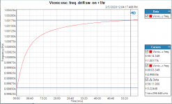
Vicnic's 1kHz oscillator cold start, initial freq. drift. Ambient was 22C, osc. in hermetically closed metal box together with SilentSwitcher.
Jan
Interesting to know. Did you happen to measure the THD level during that time period?
I have two oscillators which Victor sent me (1kHz, 10kHz) waiting for some free time when I can build some small regulated power supplies.
Mike
PS Jan - I assembled the AutoRanger II kit you shipped me and it turned out fantastic. Can't wait to try it out on the next amplifier I need to test. Thanks.
Last edited:
Interesting to know. Did you happen to measure the THD level during that time period?
I have two oscillators which Victor sent me (1kHz, 10kHz) waiting for some free time when I can build some small regulated power supplies.
Mike
PS Jan - I assembled the AutoRanger II kit you shipped me and it turned out fantastic. Can't wait to try it out on the next amplifier I need to test. Thanks.
No I didn't check THD at that time.
BTW I run my Vic oscillators from a SilentSwitcher (currently sold out but coming end of May to the diyaudio store again!)
Jan
Vicnic's 1kHz oscillator cold start, initial freq. drift. Ambient was 22C, osc. in hermetically closed metal box together with SilentSwitcher.
Jan
Thanks, Jan! Good work. On the other side, how confident are we in your measurement clock? The maddening things that happen when we add too many zeros to our goals.
")
I can't remember what sort of bin size you were aiming for, but might be a case of needing to go to heroic insulation to get the drift down to nothing. Drill a couple holes in a styrofoam cooler and fire the thing up in the morning before afternoon experiments.
Hopefully by then you'll be in wobble-land rather than a clear exponential decay regime.Vicnic's 1kHz oscillator cold start, initial freq. drift. Ambient was 22C, osc. in hermetically closed metal box together with SilentSwitcher.
Jan
Please provide figures about 1min may to 60min, while measuring this may shows the beef.
Hp
David's board is also very good. I don't remember any significant performance fall off that was enough to show on the different analyzers I tried. Verifying performance at the extremes is really hard.
Is there a schematic of David's design available. I have SN 001 of his which he built for me.
THx-Richard Marsh
I wonder if modifying an oscillator to form a very narrow tuning range VCO might be a surer path to a stabilized, low-distortion oscillator; the VCO would be phase-locked to the sampling clock with conventional PLL techniques.
Victor’s superlative oscillator seems an obvious, easily available choice. I extend profound apologies to Victor for suggesting abuse of his outstanding design.
I refer to his schematic (post #8254 above) in the following discussion. I propose Vactrol-type opto-couplers to adjust frequency tuning.
Initially, assume a single coupler in parallel with R29 and that its control current is adjusted to lower the combined resistance of the R28, R29, and coupler by 1%. The oscillator frequency will rise 0.5%, but the gain of the filter (IC2a) will also fall 0.5%. The lowered gain would compel the FET loop-gain ALC circuit to increase its gain 0.5% to accommodate and would likely degrade carefully optimized distortion---the larger the required frequency shift the larger the stress on gain control.
To avoid the interaction of filter gain with frequency, consider three identical couplers paralleled with R29, R20, and R21. Now that same coupler control current will raise the oscillator frequency a full 1% and filter gain will be unchanged.
To minimize distortion introduced by photocell nonlinearity, amplitude across the cells should be held to the minimum required to compensate frequency drift. This in turn implies that cell resistance should be as low as is practical. To convince myself that distortion might be acceptably small, I explored a tentative paper design and I offer the details for scrutiny and discussion. What follows is estimation of 2nd harmonic distortion resulting from cell nonlinearity alone; all other distortion mechanisms are course still present but ignored here.
From readily available couplers, I suggest that a reasonable cell resistance is about 40 ohms at 20mA control current. I assume a fixed 240 ohm resistor in shunt with the cell, yielding about 34 ohms 20mA. In turn, I assume 68 ohms at center of range, 102 ohms as an arbitrary maximum for analysis--- i.e. 68 ohms +/- 34 ohms.
Victor indicated in post #8284 that his oscillator output is 7.5V pk-pk, equal 2.65V rms. Nominal resistance of R29+R29 is about 16K. When cell resistance is 102 ohms, cell amplitude would be about 48mV pk-pk (17mV rms) and 12mV pk-pk for cell at 34 ohms. Voltage-controlled tuning range would be very restricted--- about 0.4% pk-pk, about 4Hz @ 1kHz. Photocell amplitude would thus range between 43 dB and 55 dB below the 7.5V output.
Attached below is an excerpt from an old Vactec data book. The text indicates distortion is typically below -80dBc re 500mV rms cell amplitude, and that cell distortion is chiefly 2nd harmonic. Judging from the accompanying graphs, the description seems conservative; however, these devices aren’t available for easy purchase and I have no data for the candidate devices I suggest below. None-the-less, I’m adopting the -80dBc re 500mV benchmark for guesswork analysis.
The assumed cell voltage of 17mV is 29.3dB below 500mV; because 2nd harmonic is square law, expected cell distortion will drop from -80dBc an additional 29.3dB, equal -109.3dBc re 17mV.
17mV is 43.86dB below max 2.65V oscillator output, so estimated 2nd harmonic amplitude due to photocell non-linearity is -109.3dB -43.86dB = -153.2 dBc re 7.5V pk-pk. By similar analysis, if tuning values were trimmed to cell resistance of 34 ohms (near the lower extreme of available control range), estimated 2nd harmonic amplitude due to photocell non-linearity would drop an additional 12 dB to -165.2 dBc. So there is ample incentive for making the fixed tuning resistors easily adjustable.
Neglected is the fact there are two optocouplers (actually three: one cell plus a paralleled pair) adjusted in tandem. Because the cells have predominant 2nd harmonic distortion, I suspect that there might be partial cancellation of distortion--- several layers of uncertainty here and distortion actually might be worsened. Additionally, the filter stage provides very modest attenuation of the 2nd harmonic, also ignored.
Attached is a marked-up version of Victor’s oscillator with suggested modifications of his nominal resistor values and proposed added components. Again, my deep apologies to Victor. I’m imagining it might be possible to use one of his modules with factory-confirmed performance as the oscillator platform and to introduce the VCO tuning components as “air-wired” additions.
I suggest two hex-coded switches to provide fine scale adjustment of tuning resistance. This should allow tweaking of frequency and/or filter gain to minimize distortion-inducing stress on the voltage tuned elements. As a first guess, hex switches are scaled to 1Hz steps when switches are incremented in unison and would provide about 16Hz adjustment in nominal center frequency. A link to hex coded switches:
16 Position Rotary Switches Coded Rotary Switches | Mouser
Suggested optocouplers are Advanced Photonics NSL-32SR2S, available at Digikey. These are graded unto selected lots. I’m not sure how they are specified at order time, but I believe any of them should be acceptable assuming that each set of three is drawn from the same lot. This order detail would need to be resolved with the distributor.
I recommend making the ALC control voltage on IC1a-pin1 available as an external test point. This and a similar test point on the VCO tuning line will be useful in monitoring the state of the ALC and PLL loops and provide for easy tweaking of the Hex-coded switches. The R/C filters should help guard against EMI ingress.
BTW, the oscillator’s ALC voltage when first received (before any mods) should be recorded, as it is likely a near-optimum bias voltage and should be a target value during later tweaking.
The final attachment below is a sketch of the PLL control circuit, mostly block diagram detail at present. The optocoupler LED leads from the oscillator section are brought out as two separate controls and driven by transistor current sources, one of them adjustable via a trim pot. This may prove to be an unnecessary complication, but it does provide the ability to trim tracking between the two coupler sets. The adjustment procedure is to adjust the current source for minimal variation of the ALC as the VCO is tuned through its entire control range.
The oscillator section must be well shielded from the PLL circuitry due to its fast digital signals. The PLL can be implemented with “discrete” logic or perhaps with Analog Devices ADF4002. The later is more flexible (especially dividing a wide variety of A/D clock frequencies to the 1KHz loop reference) but requires the addition of driver software/hardware.
Comments are welcome. If advised that I’m insane, it won’t be the first time.
Anyone want to pursue these ideas into practice? I regret I won’t be able to offer on-the-bench support (at best, not for several months), but I can offer advice. I’ve designed many PLLs at component level and have a technical lifetime of experience in low-noise, wide-dynamic-range projects.
Regards to all,
Steve
Attachments
I wonder if modifying an oscillator to form a very narrow tuning range VCO might be a surer path to a stabilized, low-distortion oscillator; the VCO would be phase-locked to the sampling clock with conventional PLL techniques.
Victor’s superlative oscillator seems an obvious, easily available choice. I extend profound apologies to Victor for suggesting abuse of his outstanding design.
I refer to his schematic (post #8254 above) in the following discussion. I propose Vactrol-type opto-couplers to adjust frequency tuning.
Initially, assume a single coupler in parallel with R29 and that its control current is adjusted to lower the combined resistance of the R28, R29, and coupler by 1%. The oscillator frequency will rise 0.5%, but the gain of the filter (IC2a) will also fall 0.5%. The lowered gain would compel the FET loop-gain ALC circuit to increase its gain 0.5% to accommodate and would likely degrade carefully optimized distortion---the larger the required frequency shift the larger the stress on gain control.
.......
The oscillator section must be well shielded from the PLL circuitry due to its fast digital signals. The PLL can be implemented with “discrete” logic or perhaps with Analog Devices ADF4002. The later is more flexible (especially dividing a wide variety of A/D clock frequencies to the 1KHz loop reference) but requires the addition of driver software/hardware.
Comments are welcome. If advised that I’m insane, it won’t be the first time.
Anyone want to pursue these ideas into practice? I regret I won’t be able to offer on-the-bench support (at best, not for several months), but I can offer advice. I’ve designed many PLLs at component level and have a technical lifetime of experience in low-noise, wide-dynamic-range projects.
Regards to all,
Steve
Hi Steve,
This is a really excellent post, and I think you are pretty much right on target, at minimum with the concept of PLL control of frequency. There are numerous ways to make an oscillator into a VCO with very limited range, but the approach you have suggested here is well-thought-out. As you have recognized, the key issue is being able to change the frequency even a little bit without compromising the distortion of the oscillator. Earlier in this thread there was discussed some sort of injection locking; it had immediately occurred to me that a PLL approach was likely to be much better. I did lots of PLL stuff back in the 70's and 80's and even got into some debates about injection locking vs PLL for timing recovery in digital transmission systems.
One half-crazy approach might be to employ a stereo motor-driven linear pot to control the frequency of the Wein Bridge. The pot would need to have only about a 1% influence on frequency over its whole range, so its distortion contribution could be kept very low. Due to the speed limitations of the pot, loop dynamics could be challenging. However, any PLL approach will have some loop dynamics challenges due to the significant filtering needed on the output of the phase detector. Of course, to achieve tight control of the oscillator frequency for testing purposes, the loop does not need to be fast-acting. On the PLL topic, the phase detector would likely not want to be of the switching variety, but rather based on a clean analog multiplier.
As a fan of state variable oscillators and filters, I have also wondered if a state variable oscillator built with the same care, good components and attention to details as Victor's, could achieve the same level of performance. I say this for 2 reasons. First, I think it is generally true that it is easier to control the frequency of an SVO than a Wein bridge oscillator, especially without degrading distortion performance. Secondly, the natural availability of a quadrature output from an SVO might provide some advantages to the PLL implementation.
The availability of the quadrature output in a SVO can also be used to advantage in the oscillator agc circuit. There, for example, we can create a four-phase amplitude rectifier to greatly reduce ripple amplitude and force the primary ripple frequency to four times the oscillator frequency. Of course, the nonlinearity of the agc control element is still there to deal with.
Finally, one would likely want to put the frequency reference and PLL circuitry in an entirely separate box from the oscillator.
Cheers,
Bob
Very interesting discussion above, thanks guys!
My € 0.02: for the tracking notch (almost ready for publication ;-) I use an NSL32-SSR3 linear optocoupler in series with 8k resistor as control element.The Opto has a nominal R of about 200R and varies +/-100R. With the 8k series R that provides a freq tuning range of about +/-5Hz, more than enough.
The NLS has about -120dB distortion at voltages below 50mV. It sees about 25mV signal with 1V signal in the flter. Because its distortion contribution is attenuated with the ratio beween its R and the 8k series R, the result is below -140dB.
Something similar should be possible with the oscillators discussed above as well, maybe able to push it down to -150dB.
I expect to be testing 2nd prototype next week.
Jan
Thank you, Bob and Jan.
I too thought about ganged servo-control pots, but fretted about servo sticking and pot wiper noise, etc. Might be more benign than I fear. I also thought about two-section air-variable rotary capacitors. Almost sure to not introduce distortion, but probably susceptible to microphonics and the same mechanical servo paranoia. I thought LDR be less of a science-fair project.
I too thought about ganged servo-control pots, but fretted about servo sticking and pot wiper noise, etc. Might be more benign than I fear. I also thought about two-section air-variable rotary capacitors. Almost sure to not introduce distortion, but probably susceptible to microphonics and the same mechanical servo paranoia. I thought LDR be less of a science-fair project.
Hi bend,
Oh, but you did think of it too!
We had similar thinking, but you were clearly first to post the notion.
Regards,
Steve
Oh, but you did think of it too!
Would a single resistor value change to change the frequency 1 Hz have a significant effect on distortion? Worst case, change the appropriate two resistors in tandem. The change could be done with FETs (with appropriate series/parallel resistance full-on to full-of makes for 1Hz change). If the slightly non-linear FET resistance adds too much distortion, replace it with switches in a binary arrangement to provide linear step changes in resistance.
Switches could be FETs, CMOS DG series, or maybe reed relays. A "vactrol" LED/LDR combo is nice and continuous like using a FET as a variable resistance, is probably a more linear resistance than a FET, but a slower response. Since it's compensating for quite slow (presumably thermal) changes, the slower response shouldn't matter.
We had similar thinking, but you were clearly first to post the notion.
Regards,
Steve
Hi Steve,
This is a really excellent post, and I think you are pretty much right on target, at minimum with the concept of PLL control of frequency.
The availability of the quadrature output in a SVO can also be used to advantage in the oscillator agc circuit. There, for example, we can create a four-phase amplitude rectifier to greatly reduce ripple amplitude and force the primary ripple frequency to four times the oscillator frequency. Of course, the nonlinearity of the agc control element is still there to deal with.
Finally, one would likely want to put the frequency reference and PLL circuitry in an entirely separate box from the oscillator.
Cheers,
Bob
Bob-
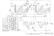
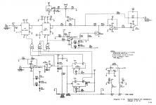
FWIW attached are the schematics of the Boonton 1120 (21, 10) source board. its a state variable oscillator with a very precise leveling loop as you suggest. It uses analog multipliers for both level and frequency trim. There is a Z80 and a TXCO for measuring the frequency and a DAC for the fine tuning.
Its an older design and shows some of the limitations from the 1980's when it was designed. There are a number of limitations but still had great potential. Biggest issues are the analog multipliers. need to find better ones that can be retrofitted. Then the nonlineatity of the Jfets. Early 1120's used a PN4391 with 30 Ohms RDS. Later use a J108 with a lower RDS and the distortion contribution is clearly lower.
I just did some measurements on some J108's as switches. With a 4.7K resistor to source and a 600 Ohm 3V source I get about .1% 2nd @ 20 mV across the fets. Lower Rds on (ranges from 4 to 5 Ohms on the samples I'm testing) correlates with lower distortion. If used with a 5K resistor the nonlinearity should be attenuated by 60 dB or below -120 dB. Still selecting will be important.
Attachments
What can I say, great minds think alike!Hi bend,
Oh, but you did think of it too!
We had similar thinking, but you were clearly first to post the notion.
Regards,
Steve
- Home
- Design & Build
- Equipment & Tools
- Low-distortion Audio-range Oscillator