Demian, what model did you get? 725-D I hope.
-Richard
No an AM70A which is a newer design but shares a lot.
No an AM70A which is a newer design but shares a lot.
It resembles the Panasonic VP-7722A in most ways -- made and maybe designed also by Mitsubishi Heavy Industries. Says tag in rear panel.
The 7722 used 2 notch filters. Does THD/THD+N and IM and has built in generators.
What makes the 725D most useful is the monitor output is scaled with the instruments range. It is not with the 7722 which makes the monitor much less useful.
Is the monitor port (residual distortion) scaled to the AM70 instrument's range setting?
7722

-Richard
When I see something that far beyond good I would check the system. Specifically add a marker of known level in the same general range. You can add it via a resistive attenuator to the 600 Ohm output of Victor's oscillator. There are so many things at those levels that can confuse a measurement. I have been burned too many times.
One possibility that did happen to me was that the drift was enough that the averages eliminated the harmonics. 32 X 1.2M would be something like 13 minutes for the measurement. The bins are .04 Hz and my Victor oscillators all drift more than that in 13 minutes as does all my other analog oscillators.
One possibility that did happen to me was that the drift was enough that the averages eliminated the harmonics. 32 X 1.2M would be something like 13 minutes for the measurement. The bins are .04 Hz and my Victor oscillators all drift more than that in 13 minutes as does all my other analog oscillators.
When I see something that far beyond good I would check the system. Specifically add a marker of known level in the same general range. You can add it via a resistive attenuator to the 600 Ohm output of Victor's oscillator. There are so many things at those levels that can confuse a measurement. I have been burned too many times.
One possibility that did happen to me was that the drift was enough that the averages eliminated the harmonics. 32 X 1.2M would be something like 13 minutes for the measurement. The bins are .04 Hz and my Victor oscillators all drift more than that in 13 minutes as does all my other analog oscillators.
Yes good idea to add a marker. I don't think the drift is an issue as it would probably widen the fundamental spike.
The figures of the eqiupment lineup support the measnurement though.
I'll be back!
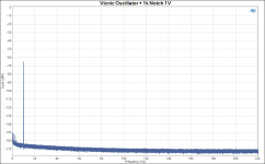
OK, first the Vicnic oscillator drift. I confirm by direct freq measurement it drifts a few Herz over 15 or 20 minutes after switch-on. The attached confirms that.
The wide fundamental is from the Vicnic, the narrow from the AP generator. Both 32 averages at 1.2Msamples FFT.
Jan
The wide fundamental is from the Vicnic, the narrow from the AP generator. Both 32 averages at 1.2Msamples FFT.
Jan
Attachments
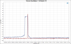
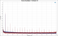
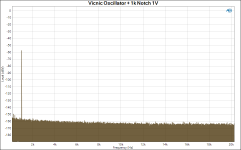
Finally, here is the Vicnic again but now a single sweep to exclude cancellation of harmonics due to oscillator drift. Clearly no harmonics above the floor.
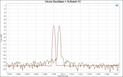
And a blowup of the two fundamentals, with a single average for the Vicnic.
This is one hell of an oscillator and with the passive twin to decrease the dynamic range requirement for the AP ADC, gives truly stellar performance.
Jan
And a blowup of the two fundamentals, with a single average for the Vicnic.
This is one hell of an oscillator and with the passive twin to decrease the dynamic range requirement for the AP ADC, gives truly stellar performance.
Jan
Attachments
Last edited:
Finally, here is the Vicnic again but now a single sweep to exclude cancellation of harmonics due to oscillator drift. Clearly no harmonics above the floor.
And a blowup of the two fundamentals, with a single average for the Vicnic.
This is one hell of an oscillator and with the passive twin to decrease the dynamic range requirement for the AP ADC, gives truly stellar performance.
Jan
")

-RNM
You have to build an oven for the oscillator. I am currently planning one.OK, first the Vicnic oscillator drift. I confirm by direct freq measurement it drifts a few Herz over 15 or 20 minutes after switch-on. The attached confirms that.
The wide fundamental is from the Vicnic, the narrow from the AP generator. Both 32 averages at 1.2Msamples FFT.
Jan
I think that there is no doubt that Viktor's oscillator is one hell of a good design: what I would like to ask is that "Is it feasible for Viktor's design to be made into a variable frequency version and what support could we, as a group, give him to try it?" Maybe starting small covering the audio bandwidth and expanding as experience is gained.
If its a crowd-funding thing - I'm in.
Regards
Mike
If its a crowd-funding thing - I'm in.
Regards
Mike
Here is the actual schematic:
https://content22-foto.inbox.lv/albums/e/elterra/OscillatorNew/Gen1kHzN7.png
The main differences from the previous one:
OPA1656 instead of LME49720
Output impedance 100 ohm
https://content22-foto.inbox.lv/albums/e/elterra/OscillatorNew/Gen1kHzN7.png
The main differences from the previous one:
OPA1656 instead of LME49720
Output impedance 100 ohm
May I ask where I can view the latest schematics, thanks.
I think that there is no doubt that Viktor's oscillator is one hell of a good design: what I would like to ask is that "Is it feasible for Viktor's design to be made into a variable frequency version and what support could we, as a group, give him to try it?" Maybe starting small covering the audio bandwidth and expanding as experience is gained.
If its a crowd-funding thing - I'm in.
Regards
Mike
Thank you, Mike
.The fixed frequency board has more advantages, and probably always will have better distortion performance, than a variable version.
I think that there is no doubt that Viktor's oscillator is one hell of a good design: what I would like to ask is that "Is it feasible for Viktor's design to be made into a variable frequency version and what support could we, as a group, give him to try it?" Maybe starting small covering the audio bandwidth and expanding as experience is gained.
If its a crowd-funding thing - I'm in.
Regards
Mike
There are 2 versions of what I would loosely call "variable". The first would be continuously variable over a decade with switched decades. Doing this is a significant level of complexity and possible performance degradation.
The second, more practical, approach is to have a set of a few chosen frequencies that are chosen by switches or relays. A typical very small group of 3 frequencies might be 50 Hz, 1 kHz and 20 kHz. Small relays could select appropriate combinations of R and C tuning elements. A larger set of 10 frequencies would be something like 20 Hz, 50 Hz, 100 Hz, 200 Hz, 500 Hz, 1 kHz, 2 kHz, 5 kHz 10 kHz and 20 kHz, e.g., a single 1-2-5 sequence covering 20 Hz to 20 kHz. Three different capacitor values might be used to set the decade and 3 different resistor values might be used to pick the frequency within the decade.
There will always be some performance degradation due to such an approach because the optimum value of resistance and reactance cannot be chosen for each selected frequency. If 10 different capacitor values were chosen to set the frequencies with a single value of resistance, this source of degradation might be smaller. However, it may remain that the optimum value of resistance and reactance may be different at higher frequencies due to phase shift and/or signal to noise considerations. If only a small group of frequencies is used, it is more practical to fully customize the resistor and capacitor values for each frequency.
There is a further potential compromise that could degrade performance in a multi-frequency oscillator. This is the fact that the oscillator agc required for each frequency may be somewhat different. This will especially be likely at the higher frequencies. This effect will increase the required agc range (e.g., operating resistance range of the JFET agc element). This in turn will tend to increase distortion and noise contributions from the agc circuit at some frequencies. Once again, a switched customized agc trim for each of a small set of frequencies would minimize this potential source of degradation. The end result is more complexity.
Finally, different values of agc filtering time constants are needed for different frequencies for optimum settling for a given level of agc-created distortion. A reasonable compromise is for each frequency decade to have its own set of agc time constants.
For a small set of frequencies, one might very well find that the best solution is to have, say, four separate oscillators for four frequencies. Then just select the output of the desired one and force the other three to be off by injecting an appropriate voltage into the agc circuit.
Cheers,
Bob
Here is the actual schematic:
https://content22-foto.inbox.lv/albums/e/elterra/OscillatorNew/Gen1kHzN7.png
The main differences from the previous one:
OPA1656 instead of LME49720
Output impedance 100 ohm
Thank you very much Viktors for kindly sharing your schematics with the diyA community, I appreciate that, and compliments from me too for your excellently performing generator!
Cheers Michael
Here is the actual schematic:
https://content22-foto.inbox.lv/albums/e/elterra/OscillatorNew/Gen1kHzN7.png
The main differences from the previous one:
OPA1656 instead of LME49720
Output impedance 100 ohm
Would 50 ohms also be possible with measuring wires below 1 meter and low capacity? Or is there a risk of degradation?
There are 2 versions of what I would loosely call "variable". The first would be continuously variable over a decade with switched decades. Doing this is a significant level of complexity and possible performance degradation.
The second, more practical, approach is to have a set of a few chosen frequencies that are chosen by switches or relays. A typical very small group of 3 frequencies might be 50 Hz, 1 kHz and 20 kHz. Small relays could select appropriate combinations of R and C tuning elements. A larger set of 10 frequencies would be something like 20 Hz, 50 Hz, 100 Hz, 200 Hz, 500 Hz, 1 kHz, 2 kHz, 5 kHz 10 kHz and 20 kHz, e.g., a single 1-2-5 sequence covering 20 Hz to 20 kHz. Three different capacitor values might be used to set the decade and 3 different resistor values might be used to pick the frequency within the decade.
There will always be some performance degradation due to such an approach because the optimum value of resistance and reactance cannot be chosen for each selected frequency. If 10 different capacitor values were chosen to set the frequencies with a single value of resistance, this source of degradation might be smaller. However, it may remain that the optimum value of resistance and reactance may be different at higher frequencies due to phase shift and/or signal to noise considerations. If only a small group of frequencies is used, it is more practical to fully customize the resistor and capacitor values for each frequency.
There is a further potential compromise that could degrade performance in a multi-frequency oscillator. This is the fact that the oscillator agc required for each frequency may be somewhat different. This will especially be likely at the higher frequencies. This effect will increase the required agc range (e.g., operating resistance range of the JFET agc element). This in turn will tend to increase distortion and noise contributions from the agc circuit at some frequencies. Once again, a switched customized agc trim for each of a small set of frequencies would minimize this potential source of degradation. The end result is more complexity.
Finally, different values of agc filtering time constants are needed for different frequencies for optimum settling for a given level of agc-created distortion. A reasonable compromise is for each frequency decade to have its own set of agc time constants.
For a small set of frequencies, one might very well find that the best solution is to have, say, four separate oscillators for four frequencies. Then just select the output of the desired one and force the other three to be off by injecting an appropriate voltage into the agc circuit.
Cheers,
Bob
Analog Precision has built something like this. As you can see from the price, it is not entirely trivial to build a variable analog oscillator that is as good at any frequency as it is at 1 kHz.
I have no data in the case of the oscillator at this moment, but in the case of the RIAA stage, the OPA1656 allows to run with any cable via 50 ohms output resistor and keeps stable. Needs to try.Would 50 ohms also be possible with measuring wires below 1 meter and low capacity? Or is there a risk of degradation?
- Home
- Design & Build
- Equipment & Tools
- Low-distortion Audio-range Oscillator