Vic, thanks for those points. I shall keep an eye on that.
As for the higher level on the cap, that depends on the test level, no? If the differential level used is the same as the single level that would be used, it's no different.
That CM needs some quantification for sure. It would be a shame if the differential twin-t would squash the mains noise, only to raise signal distortion.
Why can't we have our cake and eat it too?
Jan
In my work for the tracking notch, I found that at the levels of distortion we are talking about here, -140dB or below, any capacitive load on an opamp immediately is visible in the distortion. It doesn't impact stability, and apparently everything is fine, but the distortion gets up fast.
Using some series R on the opamp output improves it of course. But it impacts the notch depth. It's a fine balance of getting the distortion extremely low and still getting a notch depth of at least 40dB.
I would expect, but haven't tested, similar issues to manifest themselves with the active twin-t.
Jan
However, bear in mind that the active twin T does not apply a direct capacitive load to the output of the op amp. The shunt capacitor in the T goes through the series capacitors in the T before it goes anywhere else. In any case, the answer probably depends a lot on the specific op amp used.
Cheers,
Bob
Yes, but in many cases in the balance mode you can have higher differential voltage.Vic, thanks for those points. I shall keep an eye on that.
As for the higher level on the cap, that depends on the test level, no? If the differential level used is the same as the single level that would be used, it's no different.
Jan
In working on the Shibasoku twin t it was clear that the opamp driving the feedback is critical. The buffer less so. I got the best results with the lme49990. I'll be back at that shortly with the new Shibasoku I just got.
I can share a SIM of that first band elimination filter if there is interest. SIM distortion will have only a tenuous relation to reality but the filter response is accurate.
For a balanced notch using the THAT ingenious receiver with its active balancing input should address imbalance issues pretty well.
In working on the Shibasoku twin t it was clear that the opamp driving the feedback is critical. The buffer less so. I got the best results with the lme49990. I'll be back at that shortly with the new Shibasoku I just got.
I can share a SIM of that first band elimination filter if there is interest. SIM distortion will have only a tenuous relation to reality but the filter response is accurate.
For a balanced notch using the THAT ingenious receiver with its active balancing input should address imbalance issues pretty well.
Demian,
Which model did you get? I have 725D and I could never get any detailed circuit info on it.
-Richard Marsh
Demian,
Which model did you get? I have 725D and I could never get any detailed circuit info on it.
-Richard Marsh
The schematic and manual are on elektrotanya.com , there are bot checks and timers to get through. No login or $.
I just took a look at the schematic.
Notch attenuation measured with 1Vrms, is exactly as Victor have stated: passive twin T notch attenuation -9,1dB for the second H, and -5,2dB for the third H. Notch deep is -80dB.Quote:
Originally Posted by Monte McGuire
I think it'd be a good idea to just measure your notch directly. Just measure the gain at 2kHz and 3kHz and you have the conversion factors actually in your notch - no need to quote something else. I guess you need a general purpose oscillator for that, but for measuring gains, it doesn't have to be that clean at all to be useful. A sine wave generated by a computer sound card would be more than acceptable, as long as the frequency was correct. But, you can verify that using the same spectrum analyzer SW.
This is the good way for to get right scale.
I used that scheme for to calibrate the measurements with -140dB markers:
https://content28-foto.inbox.lv/albu...wMeas/Mix4.jpg
Also needs to note, that the typical passive twin T notch attenuation -9,1dB for the second H, and -5,1dB for the third H appears only in "ideal" condition, when the source impedance is "0" and no load at the notch output. In real conditions this attenuation will be higher. When the source impedance is 600 ohm, the attenuation would be app. -10,2dB for 2H, and -6,5dB for 3H.
NOTCH.gif NOTCH1.gif NOTCH2.gif NOTCH3.gif
Attachments
The schematic and manual are on elektrotanya.com , there are bot checks and timers to get through. No login or $.
I just took a look at the schematic.
That looks like the schematic I scanned and shared of the 725B. The 725D is quite different even though the circuitry is similar, but lots of SMT and amplifier modules built from discrete SMT.
I just got an AM70A. Its similar but has the oscillator contained within and also does IM. I'll post what I learn on a seperate thread.
Hi Victor,
now I see that you wrote me in september 2019.
Yes I would like to bay a new board, preferably with components.
Is that possible?
Greetings
Joost Kist
Hi Joost,
I sent you PM.
Vic.
Is this a secret information
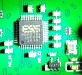
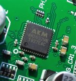
No. The boards are available by request. The actual boards looks that:
Home | ULD audio
I sent him a PM as well.Is this a secret information
In working on the Shibasoku twin t it was clear that the opamp driving the feedback is critical. The buffer less so. I got the best results with the lme49990. I'll be back at that shortly with the new Shibasoku I just got.
.
Demian, what model did you get? 725-D I hope.
-Richard
No. The boards are available by request. The actual boards looks that:
Home | ULD audio
I am also interested. Could you Pm me with the details? Regards.
Why not ebaying?I am also interested. Could you Pm me with the details? Regards.
Why not ebaying?
I assume he is only selling per request.
- Home
- Design & Build
- Equipment & Tools
- Low-distortion Audio-range Oscillator