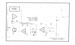
The schematic in fig. 8.4 is a bit fuzzy but readable enough.
If you can read it then why don't you post it? Obviously, if I could read it then I wouldn't ask him for a clear copy!
Thanks for the link. very useful!
Attachments
Last edited:
Because you already have it! see post 532 http://www.diyaudio.com/forums/equi...on-audio-range-oscillator-54.html#post3182358
Last edited:
Because you already have it! see post 532 http://www.diyaudio.com/forums/equi...on-audio-range-oscillator-54.html#post3182358
I'm sorry, I don't follow you. I have that manual. That's where I got the fuzzy figure. There is no figure 8.4 BTW.
Do you mean the attached schematic instead?
Attachments
I'm sorry, I don't follow you. I have that manual. That's where I got the fuzzy figure. There is no figure 8.4 BTW.
Do you mean the attached schematic instead?
Yes!
It says Fig. 8-4 in the bottom right corner
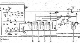
The oscillator circuit it the same as the HP339a, schematic available here: http://bama.edebris.com/manuals/hp/339a look at pgs 103-106. Much better than the HP239 scans, just chopped into several pages. Much simpler than the KH4025 circuit but slower settling.
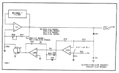
Here is a better quality 239A (simplified) schematics.
Resistor values:
Ra = 10k (X 10 range), 1k (X 100, X 1k, X 10k range)
Rb = 100k (X 10 range), 10k (X 100, X 1k range), 1k (X 10k range)
R49 = 2k
C42 = 220u
Ciao,
L.
Resistor values:
Ra = 10k (X 10 range), 1k (X 100, X 1k, X 10k range)
Rb = 100k (X 10 range), 10k (X 100, X 1k range), 1k (X 10k range)
R49 = 2k
C42 = 220u
Ciao,
L.
Attachments
Last edited:
Here is a better quality 239A (simplified) schematics.
Resistor values:
Ra = 10k (X 10 range), 1k (X 100, X 1k, X 10k range)
Rb = 100k (X 10 range), 10k (X 100, X 1k range), 1k (X 10k range)
R49 = 2k
C42 = 220u
Ciao,
L.
Thank you!
So, bear with me a minute about what they are dong here. Are they changing these resistors and capacitors for each range to change some kind of filter for each range? Are they changing the settling time based on which range is selected?
Last edited:
The oscillator circuit it the same as the HP339a, schematic available here: http://bama.edebris.com/manuals/hp/339a look at pgs 103-106. Much better than the HP239 scans, just chopped into several pages. Much simpler than the KH4025 circuit but slower settling.
Thank you!
Here is a better quality 239A (simplified) schematics.
Resistor values:
Ra = 10k (X 10 range), 1k (X 100, X 1k, X 10k range)
Rb = 100k (X 10 range), 10k (X 100, X 1k range), 1k (X 10k range)
R49 = 2k
C42 = 220u
Ciao,
L.
Now that I see this circuit more clearly, what is the input impedance for the node where CR1 connects to the output of the oscillator? Since the other end of CR1 is AC connected to ground via a capacitor Ca, I would think it would be a dead short for either some part of each cycle or for some corner frequency that I can't figure out right now. Should there be a buffer to drive this diode?
Thank you!
So, bear with me a minute about what they are dong here. Are they changing these resistors and capacitors for each range to change some kind of filter for each range? Are they changing the settling time based on which range is selected?
Generator dynamics changes with oscillation frequency, so you have to change ALC loop gain and response time in order to optimize every range for both low THD and short settling time (and stability, too) - in general a single time constant loop can't work (and actually won't) from 10 Hz to 100 kHz with standard peak detectors. Heavy filtering will guarantee low THD but very long settling time; light filtering will shorten settling time at the expense of a much higher detector injected THD - there's a trade off. In the actual 239A THD @ 1 kHz is lower in the 10 X100 range than in the 1 X1k range, but the generator won't probably work @ 10 kHz in the X100 range...
As far as the schematics is concerned, my 239A clone includes a buffer just before the full wave detector, and it performs actually measurably better than the original one.
L.
Last edited:
Are they changing the settling time based on which range is selected?
As noted in the post above, yes--a must for a high-performance oscillator. The sample-and-hold based approach makes this very easy by the use of a gated integrator. I think you should reade these two references (along with the AP System One service manual):
www.hpl.hp.com/hpjournal/pdfs/IssuePDFs/1980-08.pdf (pp. 10-11)
www.hpl.hp.com/hpjournal/pdfs/IssuePDFs/1985-12.pdf (pp. 31-35)
Settling time is actually a number expressed in cycles. If an oscillator settles in 10 cycles (which would be fast for a very low distortion implementation), it would settle in 1 s at 10 Hz and in 10 ms at 1 kHz.
Samuel
Hello David,Hi PChi,
"There are low charge injection analog switches avaliable which don't cause much pedestal error, glitches or ringing."
Can you put some numbers to this?
Thanks,
The ADG1221 claims that the Charge injection q = 0.1 pC typically.
I think that is much less than a discrete FET could achieve.
The sample and hold capacitor that I used was C = 10 nF
The voltage step, ΔV = q / C = 0.1 x 10⁻¹² / 10 x10-9 = 10 uV (theoretical).
I guess that Analog Devices are using trimming on the charge injection used to counteract the inevitable step from the gate control signals coupling through the gate to source and drain capacitance. I attached an Oscilloscope plot of the sample and hold output signal in an earlier post which shows capacitance coupling between the switch input and output at 100 kHz but not glitches.
Hello David,
The ADG1221 claims that the Charge injection q = 0.1 pC typically.
I think that is much less than a discrete FET could achieve.
The sample and hold capacitor that I used was C = 10 nF
The voltage step, ΔV = q / C = 0.1 x 10⁻¹² / 10 x10-9 = 10 uV (theoretical).
I guess that Analog Devices are using trimming on the charge injection used to counteract the inevitable step from the gate control signals coupling through the gate to source and drain capacitance. I attached an Oscilloscope plot of the sample and hold output signal in an earlier post which shows capacitance coupling between the switch input and output at 100 kHz but not glitches.
Hi PChi,
Thanks for this.
I'll look for your plot. If you are getting even 100uV out of that then it's very impressive.
I've tried a number of the sample and hold amps available with rather disappointing results.
I went the expense of the AD781 only to find it not suited to THSH AGCs. The hold step at a moderate 3V peak is around 100mV. I haven't been able to get better than a 5mV hold step with other offerings like the SMP04 + a 10mVpp ringing. Maybe the discrete approach is still a better way to go.
As far as the schematics is concerned, my 239A clone includes a buffer just before the full wave detector, and it performs actually measurably better than the original one.
L.
OK, thanks. What did you use for a buffer? I was considering a jfet input opamp like the TL051.
As noted in the post above, yes--a must for a high-performance oscillator. The sample-and-hold based approach makes this very easy by the use of a gated integrator. I think you should reade these two references (along with the AP System One service manual):
www.hpl.hp.com/hpjournal/pdfs/IssuePDFs/1980-08.pdf (pp. 10-11)
www.hpl.hp.com/hpjournal/pdfs/IssuePDFs/1985-12.pdf (pp. 31-35)
Settling time is actually a number expressed in cycles. If an oscillator settles in 10 cycles (which would be fast for a very low distortion implementation), it would settle in 1 s at 10 Hz and in 10 ms at 1 kHz.
Samuel
Thanks! I'll get to reading then.
I guess a long settling time is just an inconvenience and not a hindrance to high performance, is that right or is this more serious than that? I mean, if I have to wait a few seconds for the oscillator to settle down before taking a measurement, then that's just a few seconds of my time wasted and nothing more, right?
I come across this thread and would like to share some useful information of low-distortion sine oscillator. The information is available from a Japenese to Chinese translation. The book describes oscillators from RC based to DDS. Chapter 5 dedicates in sine wave oscillators. Section 5-1 is traditional Wien bridge. 5-2 is low-distortion state-variable osc. 5-3 is RC phase-shift osc. 5-4 is ultra low-distortion osc which has THD < 0.001 % and 1 kHz output has a -140 dBr second harmonic.
Attachments
-
low-distortion osc 6.pdf70.4 KB · Views: 169
-
low-distortion osc 5.pdf70.3 KB · Views: 182
-
low-distortion osc 4.pdf67.2 KB · Views: 162
-
low-distortion osc 3.pdf73.1 KB · Views: 145
-
low-distortion osc 2.pdf56.7 KB · Views: 174
-
low-distortion osc 1.pdf88 KB · Views: 226
-
low-distortion osc 7.pdf54.3 KB · Views: 171
I guess a long settling time is just an inconvenience.
Sure. But you have to realize that at low frequencies the effective resulting settling time quickly becomes very awkward. For a design with simple two-way rectifier and no speed-up means, one may need so heavy filtering that the settling time easily becomes 1000 cycles. This is not a problem at 1 kHz (1 s), but at 10 Hz this is nearly two minutes (which I'd consider far from acceptable).
The newer commercial generators are another story; as they are computer controlled they are also optimized for running very fast sweeps. So they try to get sub-second settling at high frequencies.
I come across this thread and would like to share some useful information of low-distortion sine oscillator.
Thanks!
Samuel
Hello,
I agree with Samuel Groner,
If you want fast settling it's hard to beat the Sin^2 + Cos^2 approach. It's particularly impressive to see the operation at 10 Hz on an Oscilloscope but distortion is high.
If you want low distortion then the sample and hold or variant of works well.
There are low charge injection analog switches avaliable which don't cause much pedestal error, glitches or ringing.
I have put the circuit board shown in post #120 in a box and bought a ShibaSoku AD725C Automatic Distortion Analyzer off Ebay.
The Distortion measured was:-
At 10 Hz and 1 kHz = 0.0004 % measured with a 30 kHz low pass filter and RMS response. The residual is mostly noise with a hint of some harmonics.
At 10 kHz = 0.0006 % measured with a 100 kHz low pass filter and RMS response. The residual is mainly third harmonic.
At 20 kHz = 0.0007 % measured with a 100 kHz low pass filter and RMS response. The residual is third harmonic with others creeping in.
The ShibaSoku is a mass of close tolerance components and reed relays. The notch filter is based on 3 cascaded Bridged-T filters. Thanks to Dick Moore's web site for an explanation of the Bridged-T notch filter.
HI PChi,
As a point of reference, the oscillator I have in my THD analyzer from 1981 settles to 0.1dB at 20Hz within 1 second and to within 0.01 or so within 3 seconds. This is for either decade changes or frequency changes within a range. Total analyzer THD at 20Hz is less than 0.006%, but I think most of that is in the analyzer side and that the oscillator is much better than that.
The SV oscillator uses a simple full-wave agc detector, but uses speed-up diodes across most of the integrator input resistance. Also, the agc detector capacitors are switched for the decade range and are all precharged by each other to the nominal operating value from whatever range was previously in use. Both of these techniques speed up settling when frequency or range is changed.
The design is shown in the THD analyzer article on my website at CordellAudio.com - Home.
Cheers,
Bob
- Home
- Design & Build
- Equipment & Tools
- Low-distortion Audio-range Oscillator