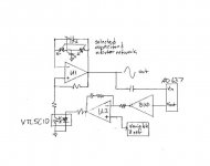
What about this one? It's a version of a bridge T oscillator I came up with that has an rms->dc converter (AD637) with a VTL5C10 as the variable element in the positive feedback leg of U1. U2 is an error amplifier and the variable Vref sets the output level. It's just an outline, obviously. Please feel free to rip it to pieces...
I just realized that the AD637 has a built in buffer, so BUF isn't needed.
I just realized that the AD637 has a built in buffer, so BUF isn't needed.
Attachments
Last edited:
Hi Dirkwright,
Thank you for your very kind words. Look for some new info on the website very soon. As you may know, I published an article in Linear Audio this month describing my VinylTrak MM/MC phono preamplifier. There is a bunch of supplemental information on the design that will go up on my website shortly.
In the meantime, if you love audio I very strongly suggest you subscribe to Jan Didden's wonderful Linear Audio publication, out every 6 months. It just hit the 200-page mark. Check it out at www.linearaudio.net - home. Jan and I will both be at RMAF in Denver, a great audio show. Jan will have an exhibit table there.
Cheers,
Bob
You're welcome. You've been in audio far longer than me.
I have purchased a couple of Jan's output and I agree they are wonderful.
This are the page of the design show in this post:
http://www.diyaudio.com/forums/equi...on-audio-range-oscillator-51.html#post3181189
Low THD Audio Oscillator
http://www.diyaudio.com/forums/equi...on-audio-range-oscillator-51.html#post3181189
Low THD Audio Oscillator
Hi DB,
This is a nice circuit, and may prove very worthwhile.
The full-wave detector in my oscillator is not a true peak detector because it has a significant 10k resistor between the FW rectifier output (from two open-emitters) and the agc filtering capacitors. This seems to work better than a true peak detector in this position.
Although I always worried a lot about the agc ripple, it does not appear to be the limiting issue in distortion in my oscillator, but rather the small distortion of the JFET in the agc. There is a noise/distortion tradeoff there. The fact that agc is not a big problem for me is partly due to the fact that that the agc filter capacitance is range-selected and that anti-parallel diodes greatly reduce the agc feedback amplitude once the oscillator has settled.
Another approach is available for reduced agc jitter, and this is a result of the beauty of the SV providing in-phase and quadrature outputs. Instead of just using a full-wave rectifier (two phases), one can use a 4-phase detector by connecting FWRs to the quadrature output as well (as long as level differences between the quadrature and in-phase outputs are close to being the same). If one wanted to go to a real extreme, they could go to 8 phase detection by combining quadrature and in-phase outputs to form yet another set of detector signals.
Cheers,
Bob
Hi Bob,
Thanks for your comment.
I wasn't singling out your oscillator as benefiting from this TH. I was just using it as an example of a very popular and high performance SVO.
I tried the quadrature peak detector approach a few years back and found that it requires
a lot of calibration. If the balance of the signal is out even a small amount from gain differences, offsets and mismatched diode the output can look very ugly. Although fluke proved that this can be a very reliable approach. I can't imagine trying it with eight.
If one wanted to get crazy with this TH it could be done with the quadrature arrangement. The quadrature stuff can get pretty noisy and requires a lot of filtering.
I'm looking for something that's simple, quiet and non intrusive to the oscillator. But I think I will be hard pressed to come up with something that outperform
your design.
I posted this circuit to see what might come out of it.
Cheers,
Last edited:
Is there any way to get any of these osc and thd meters that are built and not have to build the whole thing myself? I need sources and thd that measure well below .001% .0001 would do it for me. I have no time to make chassis and order parts and wire it and all that. is my only choise to buy an HP or A-P or the like for a lot of $$$ ??
Is there any way to get any of these osc and thd meters that are built and not have to build the whole thing myself? I need sources and thd that measure well below .001% .0001 would do it for me. I have no time to make chassis and order parts and wire it and all that. is my only choise to buy an HP or A-P or the like for a lot of $$$ ??
Hi RNMarsh,
It seems we're all in the same boat for time.
Maybe someone here would be willing to build you something.
Or just house one of Victor's.
Is there any way to get any of these osc and thd meters that are built and not have to build the whole thing myself? I need sources and thd that measure well below .001% .0001 would do it for me. I have no time to make chassis and order parts and wire it and all that. is my only choise to buy an HP or A-P or the like for a lot of $$$ ??
You're right about the $$ for decent test equipment. Not being able to afford it is why I began building the stuff myself. However, often there is a lot of good stuff on ebay - although 0.0001% THD stuff is not even widely available in commercial stuff.
Cheers,
Bob
Is there any way to get any of these osc and thd meters that are built and not have to build the whole thing myself? I need sources and thd that measure well below .001% .0001 would do it for me. I have no time to make chassis and order parts and wire it and all that. is my only choise to buy an HP or A-P or the like for a lot of $$$ ??
There are a few HP 339A's on eBay. Everything from a busted one for $120 to a bench queen for $700.
Otherwise, you could hire one of the people on this message board to build something for you.
Last edited:
Hi RNMarsh,
It seems we're all in the same boat for time.
Maybe someone here would be willing to build you something.
Or just house one of Victor's.
Speaking of Victor's oscillator, I was wondering if it could be modified to run on +/-5V instead of +/-15V. If it's ok to change the required resistors in the regulator to run on +/- 5V then I could use a couple of 9V batteries and put it in a compact box. Obviously, the output voltage would be much less but that's probably ok. As it is, it's really hard to get a compact power supply for it and 35V is a weird value that doesn't work for batteries. I got his 10kHz oscillator yesterday but I don't know what I'm going to do with it yet.
Speaking of Victor's oscillator, I was wondering if it could be modified to run on +/-5V instead of +/-15V. If it's ok to change the required resistors in the regulator to run on +/- 5V then I could use a couple of 9V batteries and put it in a compact box. Obviously, the output voltage would be much less but that's probably ok. As it is, it's really hard to get a compact power supply for it and 35V is a weird value that doesn't work for batteries. I got his 10kHz oscillator yesterday but I don't know what I'm going to do with it yet.
The opamps will run just fine on +/-5V, so I guess the rest of it will be OK also. Since a 9V rechargable battery is anything but 9volts, I guess 5V is a good value to shoot for in the oscillator.
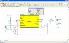
Anyone expert on the AD637 rms-DC converter? Input in above sim is 1V p-p, output from the chip is 699uV DC. I thought it should be 707mV DC?
I'm just going to have to hook it up in real life. I don't have the necessary patience for these stupid simulators!
I'm just going to have to hook it up in real life. I don't have the necessary patience for these stupid simulators!
Attachments
Last edited:
The opamps will run just fine on +/-5V, so I guess the rest of it will be OK also. Since a 9V rechargable battery is anything but 9volts, I guess 5V is a good value to shoot for in the oscillator.
Back in Jan this year Dick shipped me his Twin T to use while he was away.
I wanted a bit more headroom form it so I wired two 9V battery clips in series for the pos rail and the same for the neg rail. Not only did I get the headroom I didn't have to change batteries as often.
The opamps will run just fine on +/-5V, so I guess the rest of it will be OK also. Since a 9V rechargable battery is anything but 9volts, I guess 5V is a good value to shoot for in the oscillator.
It is one serious problem for to run my oscillators from low voltage: AGC integrator must has at least -7V...-10V on it's output, for to drive Jfet properly. It is possible to reduce this voltage app. two times, but you need make some little changes in schematic. Seems, that simplest way is to connect resistor R15 to the negative supply wire instead of GND.
Victor
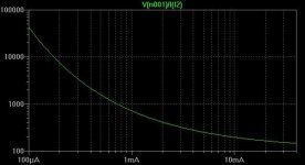
Here's an equation which describes the VTL LDR behavior --r2 is very high as the errors of a few percent are offsetting. I plugged the datasheet from the VTL5C9 into Eureqa and went to the deli for a sandwich:
An externally hosted image should be here but it was not working when we last tested it.
The lines are quite compressed at the low R end, so the errors exceed 10% as the current approaches 40mA.
Edit == Yes, there are too many parens!
Jackinnj,
I feel like I may have wasted your time a bit. When I got into the original Vactrol spice model I found it was table driven anyway. However spice only does linear interpolation between the data points which can be seen on the test plots, so I converted the model to use your equation.
To borrow your expression, that turned out to be a little above my pay grade, but I learned a few things about spice and now it works fine. It might run a bit slowly but so what. Checking the test plot (now smooth) It looks like you took the points from plot line no.2 on the spec sheet graph.
I've yet to sort out the time constants, they don't look quite right.
Simon.
Attachments
Last edited:
It is one serious problem for to run my oscillators from low voltage: AGC integrator must has at least -7V...-10V on it's output, for to drive Jfet properly. It is possible to reduce this voltage app. two times, but you need make some little changes in schematic. Seems, that simplest way is to connect resistor R15 to the negative supply wire instead of GND.
Victor
OK, thanks. I'll just leave it alone for now.
Anyone expert on the AD637 rms-DC converter? Input in above sim is 1V p-p, output from the chip is 699uV DC. I thought it should be 707mV DC?
I'm just going to have to hook it up in real life. I don't have the necessary patience for these stupid simulators!
It's not instantaneous -- and your averaging capacitor may too large. Try running the sim with an o'scope and watch the buf output increase to the RMS value.
Jackinnj,
I feel like I may have wasted your time a bit. When I got into the original Vactrol spice model I found it was table driven anyway. However spice only does linear interpolation between the data points which can be seen on the test plots, so I converted the model to use your equation.
To borrow your expression, that turned out to be a little above my pay grade, but I learned a few things about spice and now it works fine. It might run a bit slowly but so what. Checking the test plot (now smooth) It looks like you took the points from plot line no.2 on the spec sheet graph.
I've yet to sort out the time constants, they don't look quite right.
Simon.
Hi Simon,
I haven't looked at these models.
What are they using for an element? Is it R or something else?
Last edited:
Hi David,
It's a bunch of behavioural current sources but the core is a simple lookup table with entries for LDR resistance against LED current. If you have LTSpice you can have a look inside Tom Gootee's VTL5C2 model here http://www.fullnet.com/~tomg/VTL5C2.ZIP.
The models do model the response time, not sure if it's accurate.
Hi David,
It's a bunch of behavioural current sources but the core is a simple lookup table with entries for LDR resistance against LED current. If you have LTSpice you can have a look inside Tom Gootee's VTL5C2 model here http://www.fullnet.com/~tomg/VTL5C2.ZIP.
The models do model the response time, not sure if it's accurate.
Hi Simon,
I don't know if you are aware of this but in LTspice you can use an ordinary resister as a behavioral resistor. I used a resistor to do a lamp model last year and it worked quite well. A resistor might be better suited for an LDR. You can plug jackinnj's formula straight in. That would just leave you with figuring out how to do the time constants.
Cheers,
Last edited:
- Home
- Design & Build
- Equipment & Tools
- Low-distortion Audio-range Oscillator