Sam,
Nice looking board, it really does not look that complex to build, sourcing the parts will be the most time consuming effort.
What are the thin Rectangle shaped components (I believe I counted x33 of them) on the PCB? Are they SIL Reed Relays? I use 5V parts on a new DAC design I'm working on and can purchase them for about US$0.50 each (Might be cheaper) I could also arrange them for your project if your interested.
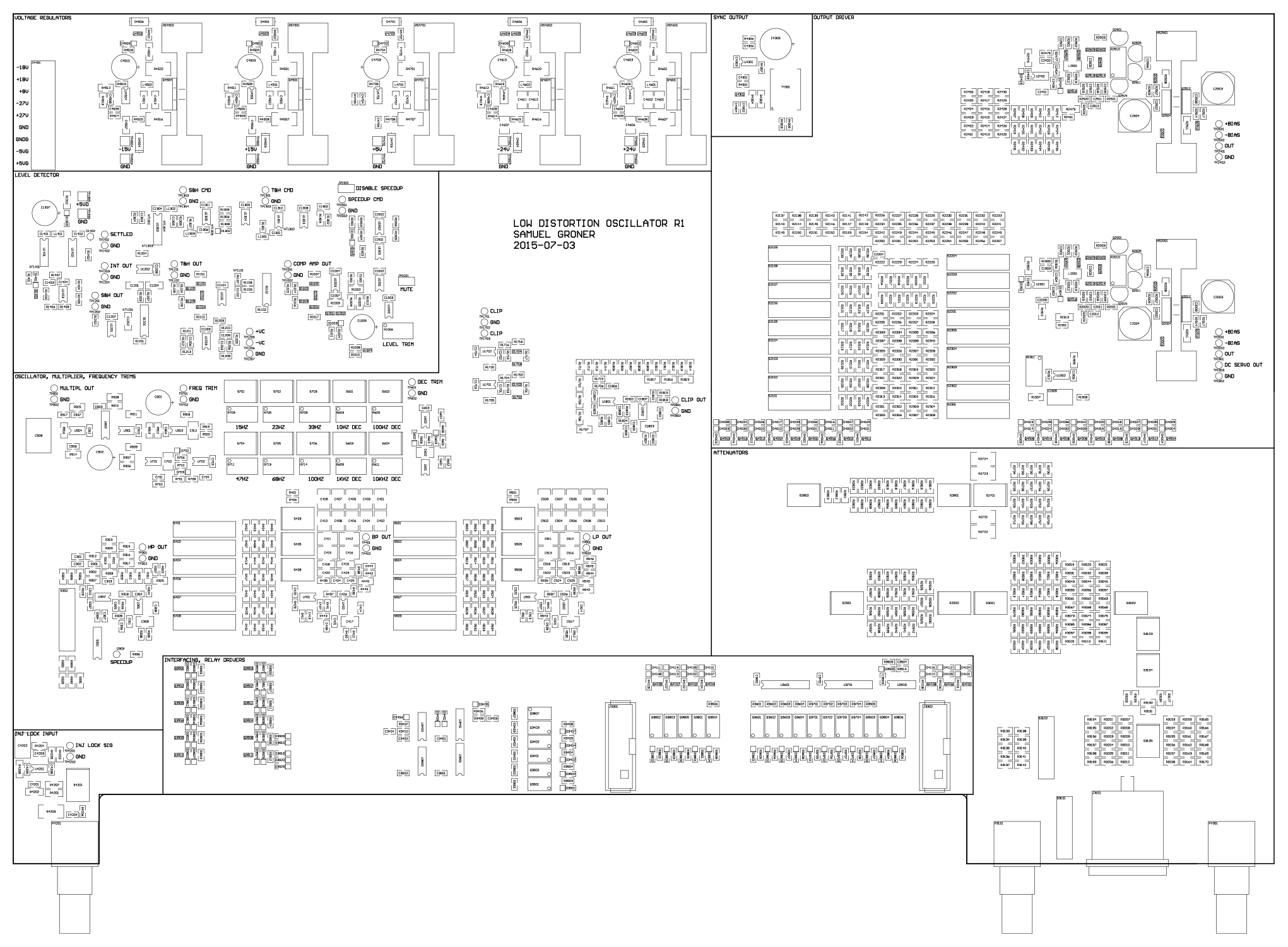
BTW, here's a preview on the PCB:
Samuel
Are there parts on the bottom too? I don't see 1800 parts there.
Nice looking board, it really does not look that complex to build, sourcing the parts will be the most time consuming effort.
I'm putting together a Mouser BOM, and all parts (except heatsinks, which I've bought from Distrelec, but perhaps there is a suitable replacement) should be standard stock.
What are the thin Rectangle shaped components (I believe I counted x33 of them) on the PCB? Are they SIL Reed Relays? I use 5V parts on a new DAC design I'm working on and can purchase them for about US$0.50 each (Might be cheaper) I could also arrange them for your project if your interested.
Yes. What type could you offer?
Are there parts on the bottom too? I don't see 1800 parts there.
Yes, but not nearly as many as on the top. Many of the large resistor banks in the output driver/attenuators are mirrored to the bottom layer to save some space. Also some other parts were placed there.
Between the largely spaced BNC connectors a frontpanel print for the user interface will be placed. This one is of course much cheaper (two layer) and far less complex.
Samuel
THD vs frequency
This is a great thread, but I've lost track of the conditions under which all of the various very low distortion figures for the various analyzers and oscillators are quoted for THD.
Should I assume that all of the quotes are for 1kHz?
1kHz is obviously one of the easiest frequencies to achieve very low distortion.
20 Hz can be quite difficult due to usually less agc filtering effectiveness on reducing agc ripple at low frequencies. This is where the rubber really meets the road for many oscillators, especially those of rather conventional design.
Are there any quotes of 20Hz THD here, and do any of them include some quote of amplitude settling time? Some HP oscillators had a switch for low distortion, but under that condition settling time to, say, 0.1dB was quite long.
Similarly 20kHz THD is more difficult to get way down than 1kHz THD. Are there any quotes here of 20kHz THD, especially if made in greater than 100kHz residual measurement bandwidth?
Finally, how do we evaluate noise in the oscillators and how good is it in these oscillators?
Such noise will certainly influence THD+N readings and the spectral widths of the harmonics. Both pase noise and amplitude noise can be issues here. 1/f noise can also be a significant issue.
The noise issue pertains especially to the agc element and the distortion and noise that it creates. As an example, a JFET agc element creates more distortion as the amount of signal voltage across it is increased. In order to get its distortion contribution down, we must decrease that signal level, but that increases its noise contribution if its agc authority (range) is held constant.
Cheers,
Bob
Samuel-
Is the injection lock isolated? My biggest problem was the hum and noise coming from a common ground. Even transformer isolation still let some through.
Bob
You are right about measuring at 1 KHz. samuel can answer about his, but he has indiicated that he found the Vishay bulk foil resistors limited the distortion at low frequencies (probably due to the differential thermal between the foil and the substrate having a time constant around 10-20 Hz). That would suggest his has been extensively tested at those frequencies.
I'll be in line to build one when he is ready to release the design.
David's board is also very good. I don't remember any significant performance fall off that was enough to show on the different analyzers I tried. Verifying performance at the extremes is really hard.
Yes. What type could you offer?
Sam,
I requested these 5V reed relays as samples about 5 years ago, so I need to reestablish contact with the company.
They are a common form factor - with the price about US0.30 to US$0.40 each.
https://dl.dropboxusercontent.com/u/86116171/SIL Reed Relay 5V.jpg
I'll be back in Asia at the end of the month so can ask sourcing dept to follow up and get the latest pricing - I'll be using them on a new DAC and AMP design so it not a problem to order extra Qtys. if the price is good.
Samuel can answer about his, but he has indiicated that he found the Vishay bulk foil resistors limited the distortion at low frequencies (probably due to the differential thermal between the foil and the substrate having a time constant around 10-20 Hz).
AP's founder & designer Bruce (Sorry I don't recall his last name) made a presentation a few years back where he also reported the same issue with LF distortion of the Bulk foils - he did a whole section of the presentation on Resistor linearity IIRC.
Its interesting as when listening to the Vishay Bulk foil resistors they have an unbeatable open soundstage, full of microdynamics, but somehow the Bass is lighter - some might say "cleaner" with less overhang, but I tend to miss the "extra bass" of other resistors.
No evidence to suggest that the measured LF thermal distortion at such low levels can be heard, but IMO they do sound a little "Bass Light"... or maybe its better to say that they introduce a sonic signature at LF.
Samuel-
Is the injection lock isolated? My biggest problem was the hum and noise coming from a common ground. Even transformer isolation still let some through.
Bob
You are right about measuring at 1 KHz. samuel can answer about his, but he has indiicated that he found the Vishay bulk foil resistors limited the distortion at low frequencies (probably due to the differential thermal between the foil and the substrate having a time constant around 10-20 Hz). That would suggest his has been extensively tested at those frequencies.
I'll be in line to build one when he is ready to release the design.
David's board is also very good. I don't remember any significant performance fall off that was enough to show on the different analyzers I tried. Verifying performance at the extremes is really hard.
Thanks Damien. I agree that measuring at the extremes is quite difficult, especially if one is attempting to get the oscillator performance without large errors due to the analyzer performance (e.g., requiring a precision passive notch filter or the like). Specification of the specific measurement conditions is also more important at the extremes.
Cheers,
Bob
AP's founder & designer Bruce (Sorry I don't recall his last name) made a presentation a few years back where he also reported the same issue with LF distortion of the Bulk foils - he did a whole section of the presentation on Resistor linearity IIRC.
Its interesting as when listening to the Vishay Bulk foil resistors they have an unbeatable open soundstage, full of microdynamics, but somehow the Bass is lighter - some might say "cleaner" with less overhang, but I tend to miss the "extra bass" of other resistors.
No evidence to suggest that the measured LF thermal distortion at such low levels can be heard, but IMO they do sound a little "Bass Light"... or maybe its better to say that they introduce a sonic signature at LF.
Thermal distortion introduced by bulk foil resistors is fairly easy to understand in an application like the feedback resistor in a power amplifier, but more difficult to see in a line-level application like an oscillator, where dissipation due to the signal is very small. Of course, this all is dependent on the wattage rating of the resistor.
Cheers,
Bob
Bob,
Would the thermal distortion not still be relative in dB terms? so irreverent to the absolute power level (we not talking about cooking the resistor beyond its thermal limits) - the effect is still present at any level (but you will drop below the noise floor a very low levels)....
Would the thermal distortion not still be relative in dB terms? so irreverent to the absolute power level (we not talking about cooking the resistor beyond its thermal limits) - the effect is still present at any level (but you will drop below the noise floor a very low levels)....
Thermal distortion in resistors follows power or voltage squared.
I guess that makes sense, suggesting that the LF thermal effects of the Vishays Bulk foils must be quite bad as it precludes there uses in precision test systems which are not operated at high power levels..
I've never bother to measure them at Low Frequency, maybe I should if my UPD has the required THD resolution at LF.
I should add that I've only experience using the Bulk foils in a line level DAC stage and more then 20 years ago a Phono stage and in both instances the "lightness of Bass" was noted...
I can't explain the subjective impression of lightness of bass when using the bulk foils, but I would guess that they contribute very little thermal modulation distortion in line level circuits.
Cheers,
Bob
Shibasoku AD725D and my dlbSVO
Bob you asked this question before in this thread and it's never been properly answered.
Here are measurement with a Shibasoku AD725D and my oscillator dlbSVO. The dlb are my initials and State Variable Oscillator.
Before presenting the measurements it is important to understand how the Shibasoku AD725D analyzer operates.
In Normal mode the analyzer operates as any other audio analyzer. The 725D ranges down to 0.0003%, -110 dBV FS of the meter. And when the meter is at full scale the monitor output is 1Vrms, 0dBV.
In Analysis mode the output of the 'Normal mode' is sampled synchronously to the input frequency. Unlike audio sampling the sampling frequency is variable with the input signal frequency. This divides the signal into phases equal to the sample rate. If I remember correctly each cycle is sampled 64 time per cycle in the low to mid frequency range. The sample rate generator is phase locked to the input signal. The samples are put through a discrete DSP where synchronous averaging is performed. Anything random like noise divided down and any constant signal is averages the same. So the noise is removed but not the signal.The processed signal is passed to a DAC and reconstructed at a fixed frequency of 488.281Hz a binary division of the 1MHz system clock. The output of the DAC is always 488.281Hz regardless of input signal frequency. This approach allows fixed tuned filters to be used on the reconstructed signal.
The Shibasoku AD725D analyses the first 10 harmonics and this is used to determine THD.
In addition the first five harmonic can be viewed individually by the push of a button and a single harmonic can be seen on the Analysis monitor output.
During these measurement I will be switching between the Normal monitor port and the analysis monitor port depending on the measurement taken. To keep things simple the range is fixed at 0.001% (-100dBV). I have an EMU0204 connected to the monitor output.
This and ARTA are calibrated for 1Vrms (0dBV) FS. Therefore FS on ARTA correspond to -100dBV. ARTA is to be read directly - 100dBV.
The measurement are as follows:
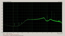
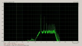
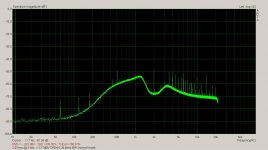
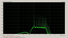
Shibasoku AD725D & dlbSVO
2.5Vrms @ 20Hz BW = 30.0 kHz -134.2 dBV THD-10, -120.9 dBV THD+N
2.5Vrms @ 1kHz BW = 29.6 kHz -138.4 dBV THD-10, -118.8 dBV THD+N
2.5Vrms @ 2kHz BW = 29.6 kHz -138.4 dBV THD-10, -117.7 dBV THD+N
2.5Vrms @ 10kHz BW = 99.6 kHz -127.0 dBV THD-10, -113.2 dBV THD+N
2.5Vrms @ 16kHz BW = 99.6 kHz -125.2 dBV THD-10, -109.9 dBV THD+N
2.5Vrms @ 20kHz BW = 500.0 kHz -123.1 dBV THD-10, -107.5 dBV THD+N
2.5Vrms @ 89kHz BW = 500.0 kHz - 99.0 dBV THD-10, - 97.6 dBV THD+N
Cheers,
1kHz is obviously one of the easiest frequencies to achieve very low distortion.
20 Hz can be quite difficult due to usually less agc filtering effectiveness on reducing agc ripple at low frequencies. This is where the rubber really meets the road for many oscillators, especially those of rather conventional design.
Cheers,
Bob
Bob you asked this question before in this thread and it's never been properly answered.
Here are measurement with a Shibasoku AD725D and my oscillator dlbSVO. The dlb are my initials and State Variable Oscillator.
Before presenting the measurements it is important to understand how the Shibasoku AD725D analyzer operates.
In Normal mode the analyzer operates as any other audio analyzer. The 725D ranges down to 0.0003%, -110 dBV FS of the meter. And when the meter is at full scale the monitor output is 1Vrms, 0dBV.
In Analysis mode the output of the 'Normal mode' is sampled synchronously to the input frequency. Unlike audio sampling the sampling frequency is variable with the input signal frequency. This divides the signal into phases equal to the sample rate. If I remember correctly each cycle is sampled 64 time per cycle in the low to mid frequency range. The sample rate generator is phase locked to the input signal. The samples are put through a discrete DSP where synchronous averaging is performed. Anything random like noise divided down and any constant signal is averages the same. So the noise is removed but not the signal.The processed signal is passed to a DAC and reconstructed at a fixed frequency of 488.281Hz a binary division of the 1MHz system clock. The output of the DAC is always 488.281Hz regardless of input signal frequency. This approach allows fixed tuned filters to be used on the reconstructed signal.
The Shibasoku AD725D analyses the first 10 harmonics and this is used to determine THD.
In addition the first five harmonic can be viewed individually by the push of a button and a single harmonic can be seen on the Analysis monitor output.
During these measurement I will be switching between the Normal monitor port and the analysis monitor port depending on the measurement taken. To keep things simple the range is fixed at 0.001% (-100dBV). I have an EMU0204 connected to the monitor output.
This and ARTA are calibrated for 1Vrms (0dBV) FS. Therefore FS on ARTA correspond to -100dBV. ARTA is to be read directly - 100dBV.
The measurement are as follows:
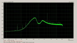
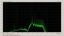
Shibasoku AD725D & dlbSVO
2.5Vrms @ 20Hz BW = 30.0 kHz -134.2 dBV THD-10, -120.9 dBV THD+N
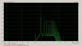
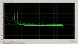
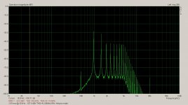
2.5Vrms @ 1kHz BW = 29.6 kHz -138.4 dBV THD-10, -118.8 dBV THD+N
2.5Vrms @ 2kHz BW = 29.6 kHz -138.4 dBV THD-10, -117.7 dBV THD+N
2.5Vrms @ 10kHz BW = 99.6 kHz -127.0 dBV THD-10, -113.2 dBV THD+N
2.5Vrms @ 16kHz BW = 99.6 kHz -125.2 dBV THD-10, -109.9 dBV THD+N
2.5Vrms @ 20kHz BW = 500.0 kHz -123.1 dBV THD-10, -107.5 dBV THD+N
2.5Vrms @ 89kHz BW = 500.0 kHz - 99.0 dBV THD-10, - 97.6 dBV THD+N
Cheers,
pics1
Attachments
-
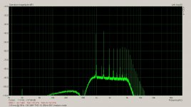 2.5Vrms @ 20Hz, -134.2dBV, THD-10 Analysis mode.JPG109.5 KB · Views: 309
 -
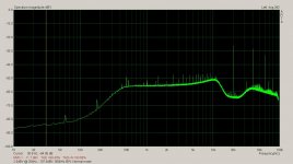
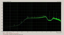 2.5Vrms 16kHz -109.9dBV THD-10, 99.6kH BW, Normal mode .JPG109.4 KB · Views: 82
 -
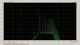
 2.5Vrms 16kHz -125.2dBV THD-10, 99.6kH BW, Analysis mode .JPG110.7 KB · Views: 88
 -
 2.5Vrms 10kHz -113.2dBV THD+N, 99.6kH BW, Normal mode .JPG106.2 KB · Views: 80
 -
 2.5Vrms 10kHz -127.0dBV THD-10, 99.6kH BW, Analysis mode .JPG109.9 KB · Views: 79
 -
 2.5Vrms 2kHz -117.7dBV THD+N 29.6kHz BW, Normal mode .JPG107.6 KB · Views: 74
 -
 2.5Vrms @ 2kHz, -138.4dBV, THD-10, 29.6kHz BW, Analysis mode.JPG109 KB · Views: 245
 -
 2.5Vrms 1kHz -118.8dBV THD+N 30kHz BW - 400Hz filter in.JPG107.3 KB · Views: 252
 -
 2.5Vrms 1kHz -138.4dBV THD-10 Analysis mode.JPG114.2 KB · Views: 303
 -
 2.5Vrms 20Hz -120.9dBV THD+N 30kHz BW, Normal mode .JPG111.6 KB · Views: 304
The Vishay design will have a sensitivity to certain transient changes. It's actually a strain gauge with a substrate matched to the resistors thermal expansion to counter the thermal coefficient. Typical of any balancing act like this there are circumstances where the substrate can't track at perfect speed.
I would guess the frequency relates to the thermal coupling g and mass of the substrate. You can scale the resistor (use larger chips) and see if it's better. Or use precision wire wound resistors (which make Vishay foils seem cheap) or use an array of more monolithic resistors as Samuel has done. You will forgo the absolute accuracy which is less of an issue in this case.
Sent from my SGH-M919 using Tapatalk
- Home
- Design & Build
- Equipment & Tools
- Low-distortion Audio-range Oscillator