Mine too. I have a 27" monitor on the PC at home but its really clumsy to use in the car.
If I weren't juggling 6 portable media devices (some of the paying work) I would get around to suppressing the tag. I find Tapatalk easier to use for navigating DIYaudio than the web interface.
If I weren't juggling 6 portable media devices (some of the paying work) I would get around to suppressing the tag. I find Tapatalk easier to use for navigating DIYaudio than the web interface.
just that I did type dBu
and all sources I can find agree that dBu is 1 mW into 600 Ohms, 0.775 Vrms
so +20 dBu is +/- 11 Vpeak - which the AD8397 does do with its +/-12 V = |24| max supply being a rail-rail output rated op amp
the AD8397 doesn't work as a unity buffer though because of input Vcm limits
I just brought it up as a high output current drive VFA since some object to the more common CFA DSL driver op amps
I'm certainly just talking about potential multiloop composite amplifier output op amp candidates - their (already low @< -90 dB) distortion is reduced by the input op amp added global loop gain - which can be huge at conventional audio frequencies which I assume is the range for these super low distortion oscillators
Last edited:
Is 3V enough? It will drive any power amp to clipping. I want more but not for good reason.
3 volts for single-ended is just fine.
David --- I'll be coming back for the summer in 3 weeks. Ship at that time.
THx-RNMarsh
There's no easy answer to this. At what frequencies and levels do you want to do your measurements? What is the expected distortion of the DUT, or the needed distortion residual of the test set? Note that you don't just need a good notch filter, the generator needs to keep up as well.
Did you use a passive notch filter? Possibly a good preamplifier after it might solve the noise issue.
For amplifiers with flat frequency response it is also possible to enhance the measurement resolution by looking at the input-output difference signal of the DUT (google Cordell distortion magnifier).
Samuel
Hi Samuel,
Per my experience with AP ATS-2. This equipment can not be trust when a low distortion signal is feed to it. Here low distortion means 1kHz fundamental signal with ~-130dB harmonics.
I've done a experiment on my preamp:
1. set the peramp to unity gain.
2. SE signal source from AP 2Vrms. (20ohm source impedance)
3. AP analyzer CH1=preamp output -- GND, (100k ohm impedance balanced)
4. AP analyzer CH2=preamp input --preamp output, (100k ohm impedance balanced)
5. Adjust the preamp gain until the voltage monitor of CH2 to lowest level (with notch filter 1kHz on AP)
and then, I got the following measurement result:
CH1=preamp output with AP source distorion plus AP anayzer distortion
CH2=??? (residual distortion of preamp only?)
BR
Paul Lu
Attachments
3 volts for single-ended is just fine.
David --- I'll be coming back for the summer in 3 weeks. Ship at that time.
THx-RNMarsh
I put together a temporary enclosure for it. It's almost complete. No room for error as I'm out of material. Tedious work.
Per my experience with AP ATS-2. This equipment can not be trust when a low distortion signal is feed to it. Here low distortion means 1 kHz fundamental signal with ~-130dB harmonics.
Measurements at the -130 dB harmonics level are very difficult--it's at the edge of what can be done with the SYS-2722 (near 1 kHz at least, no chance below ~100 Hz and above ~5 kHz). As noted already I can't give an easy solution because there isn't one. Both source and analyzer would need to be independently specified for < -140 dB performance for reasonable measurement uncertainity. Currently there's no fully worked out design available (neither DIY nor commercial) which would consistently support this performance level.
If fixed 1 kHz fits your needs you might check Victor's oscillator (there must be a link to it in this thread).
Samuel
I don't find either of the LME49600/10 all that compelling when you look at the datasheet - how is 10 dB 100 MHz peaking pretty free of problems?
the distortion of the buffer itself isn't speced, only inside another op amp loop
the "stable with any Cload" is from having the output series resistance built in to the supply chip - and not speced on the DS either
the AD8397 is a VFA just capable of +20dBu 50 Ohm drive but has 24V(+/-12) max rating and "only" 69 MHz GBW
I have used this chip - and it does blow up - the thermal protection isn't fast enough for some conditions
The series resistance is built into the chip but still inside the feedback loop, so it does not increase the output impedance, yes? Is there a reason this technique is not used by the ADSL/CFA datasheets?
the series R of the unity buffer chip isn't inside the buffer's feedback loop
but yes unity buffer r_out is inside the Global feedback loop in the DS circuits and its effect on audio frequency z_out of the composite amp is reduced by the op amp's gain
but the buffer r_out reaction with any Cload adds phase shift to the Global feedback loop - potentially destabilizing it
you don't want extra r_out inside your feedback loop because of the stability issue - better to decouple from the Cload outside the/all/any feedback loop - if you need to drive Cload then the usual series R||L can be made to work
Hello,I got confused earlier looking to get to 10V RMS (+20 dBV). For most efforts 7.7V would be enough. Will the distortion be compromised running so close to the rails?
U might try cascoding the opamp power rails off of the output in order to get higher voltage output.
Osc testing - new design by David
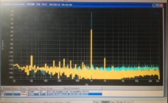
Well I got your nice box with osc inside. I am powering it with a HP 6237B power supply. I did a quick THD test using the Panasonic VP-7722A analyzer: Right out of the box without using your software... the output freq was 366.66Hz at 2.5v rms. The THD was showing -125db or about .00006%... at 3H and above... all were at -140dB. Good beginning. So next is to install your USB control software and take a closer look with the Audio Precision 2722.")
THx-RNMarsh
I put together a temporary enclosure for it. It's almost complete. No room for error as I'm out of material. Tedious work.
Well I got your nice box with osc inside. I am powering it with a HP 6237B power supply. I did a quick THD test using the Panasonic VP-7722A analyzer: Right out of the box without using your software... the output freq was 366.66Hz at 2.5v rms. The THD was showing -125db or about .00006%... at 3H and above... all were at -140dB. Good beginning. So next is to install your USB control software and take a closer look with the Audio Precision 2722.
THx-RNMarsh
Without the software running the Mdac's might be in a random state. 100Hz is the start up frequency then it should switch to 1kHz. If the Mdac's are in a random state they are unbalanced and the distortion might be higher because the oscillator sections are unbalanced and will likely have an unbalanced level from BP to LP. The right side BNC is the LP output and should have the lowest distortion.
Good start.
Cheers,
What kind of output driver did you finally use? Or is that without any? Looking forward to see the measurements!
Samuel
Hi Samuel,
This is without a driver.
Just putting some test boards together for that.
Cheers,
I cant get the software to run. Which version of Windows did it work on?
-RM
It works on Win7 and XP.
If it won't run you probably don't have .Net (dotNet) installed. You might think you do but it doesn't come with a Windows install. You have to download .Net from Microsoft's web site and install it.
- Home
- Design & Build
- Equipment & Tools
- Low-distortion Audio-range Oscillator