Next round of troubleshooting, no more shotgunning-
1) look for external causes (the computer monitor and other switching supplies are candidates. Turn off the power while connected to the scope and if the errant noise goes away its in the circuit. If not its external. My Metcal iron gets into everything with its 27 MHz drive. I have learned how to spot it.
2) find where the energy level of the oscillation is strongest. I think you said on the cathode of the TL431. Figure out the loop back to the input of the TL431, two paths. First through the main output and the 10K // 100uF low pass filter. I doubt much will get through there. To verify increase the 1K to 10K which would reduce the gain, Its remotely possible the oscillation is above the self resonance of the cap. A .1uF ceramic in parallel should eliminate that possibility. The second is the cap from the cathode (positive terminal) of the TL431 to the reference. You can try removing it and try turning it into an RC network so that the loop gain is less than 1 at 180 degree phase shift.
3) Read this (I am now) http://www.ti.com/lit/an/slva482/slva482.pdf It suggests that no cap or more than 5uF cap across the output (Cathode to anode) is required for stability in all cases. It can't hurt to try it. Your operating at 15V I am at 3.3V so the conditions are different. In the simulation if I remove C12 in your schematic and replace it with a cap from the positive terminal to ground it works great (maybe better).
Do try the trick with the LM317/337. Tie the adj pin of the 317 to the cathode of the TL431 and it will maintain approx 2V across the two transistors. Same for the LM337- except its the anode end of the Zener diode. In the simulation I'm getting 110 dB+ line noise rejection.
I'll bundle the sim and the two regulator models into a zip and upload them shortly.
I've found the output of the LM337 oscillating hard at about 20kHz 200mVpp sawtooth waveform. I hadn't looked there. It doesn't show up on the output of the negative reg. I think it's upsetting the positive side.
Good work. Once something starts it gets into everything. The negative 3 terminal regulators are much harder to stabilize. Something about building them with NPN transistors but upside down.
On page 7 of the LT337 datasheet: http://cds.linear.com/docs/en/datasheet/137Afb.pdf are some guidelines for caps.
Here is the model for the dual regulator and the 3 terminal regulators.
To install the models so you can run the simulation, extract the files from the zip and save LM317.sub, LM337.sub to the SUB folder in LIB, Save LM317.asy LM337.asy to the MISC folder, which is under the SYM folder in LIB. If your running Win7 this will need elevated privileges. I use Teracopy TeraCopy for Microsoft Windows - Code Sector which helps work around this annoyance.
To install the models so you can run the simulation, extract the files from the zip and save LM317.sub, LM337.sub to the SUB folder in LIB, Save LM317.asy LM337.asy to the MISC folder, which is under the SYM folder in LIB. If your running Win7 this will need elevated privileges. I use Teracopy TeraCopy for Microsoft Windows - Code Sector which helps work around this annoyance.
Attachments
So it turns out it was the oscillating 337. Might have a bad cap in there causing it shut down and start up again or it just a bad regulator. I'll try another first and then the caps.
I'll try your 317/337 tracking method. Tracking the output is causing a lot of bouncing around less than 100uV, But it was more stable with fixed resistor on the 317.
Thanks for all the input everyone.
I'll let you know how it goes Demian.
Oh ya and what about those schematic errors. You'll have to point them out. I can't see them myself.
Here is the model for the dual regulator and the 3 terminal regulators.
To install the models so you can run the simulation, extract the files from the zip and save LM317.sub, LM337.sub to the SUB folder in LIB, Save LM317.asy LM337.asy to the MISC folder, which is under the SYM folder in LIB. If your running Win7 this will need elevated privileges. I use Teracopy TeraCopy for Microsoft Windows - Code Sector which helps work around this annoyance.
So that 1uF cap is supposed to be across the anode - cathode and a not ref - cathode.
Oops that one went on the board. Oh well a cut here and a jumper and it's fixed.
I'll fix it on rev 1.
Very nice Demian right about 2V. I've now have 10uVpp in a 29kHz bandwidth on the Tek 7A22. About 30uV of low frequency drift. I take it that's normal?
The transformers I'm using are putting out a quasi square wave. In another word it's saturating a bit. Doesn't seem to be upsetting things though.
The transformers I'm using are putting out a quasi square wave. In another word it's saturating a bit. Doesn't seem to be upsetting things though.
Very nice Demian right about 2V. I've now have 10uVpp in a 29kHz bandwidth on the Tek 7A22. About 30uV of low frequency drift. I take it that's normal?
The transformers I'm using are putting out a quasi square wave. In another word it's saturating a bit. Doesn't seem to be upsetting things though.
Great results. Possibly limited by the noise of the 7A22. I had to build a special fixture to see the noise actually.
Is there a period to the 30 uV drift? It could be anything, including air currents. You should use a 7A13 if you have one to measure it. The 7A22 is not that stable. I know of no opamp that would even sense such a small change in its supply.
If the transformer is saturating it will buzz and get hot. Is there other filtering upstream? I have a circuit that does that intentionally. It effectively limits the peak currents through the diodes getting a power factor of .95. It really helps but its not cheap or easy to implement.
The transformers are semi torroid wound in a so called humbucking. I think it's just the nature of them. No loud buzz from them. Actually they are pretty darn quiet. If they are anything like ferromagnetic transformers then the clip should turn to a sine under heavier loading.. They weigh a ton for there size. They don't get hot at all.
I have a 7A26 and a 7A18. No 7A13. The drift is probably the 7A22. I have it AC coupled for this test. The 7A22 bounces around at it's best but it's a great PI. The drift I'd estimate at 1/2 second. It's no big deal but I'm a purest and want my electronic to be perfect which it's not.
I solved the LM337 oscillation problem. First the 337 doesn't like oscons as an output filter. Second I had to use a 100uF cap to get it to settle, actually a 47uF worked but the 100u is better. The oscon is okay for the program pin filter.
The actual rms noise will be more inline with your specs. It's mostly high frequency noise. It gets very thin as the bandwidth is narrowed.
It's slow to rise at turn on but this is is okay for a soft turn on. I was shooting for high ripple rejection and it has surpassed that. There simply isn't any.
Now to tweak the negative side.
So you say it's best with a 100k in series with a 1uF around the op amp. I'll try this.
Last edited:
For probably 10X the complexity (and 1000X the cost) we can get the drift into the .1 PPM range. I think it would make the same difference an atomic clock makes over a good crystal in digital audio. Bragging rights but no detectable improvement.
The 7A22 drifts. I have 2 and they both wander. The 7A13 is better but you really need a long scale DVM and Excel to actually quantify it.
The soft start is the price of admission. It shouldn't be an issue in most applications (your not making anything where the turn on must be flawless, like an explosives trigger are you?).
On your schematics the programming resistors for the three terminal regulators will get you maybe 4V. The way its drawn led me to some confusion on how that all worked. While bootstrapping from the output is ok it also is a path for the noise from the 317 to get into the main output and at low currents will cause the regulator to shut down and leave the load to the 317/337. You have a 10K resistor in series with the - input of the opamp. That will add an offset voltage from the input bias current and noise, its not really necessary. If needed you then need a matching resistor on the positive lead.
For probably 10X the complexity (and 1000X the cost) we can get the drift into the .1 PPM range. I think it would make the same difference an atomic clock makes over a good crystal in digital audio. Bragging rights but no detectable improvement.
The 7A22 drifts. I have 2 and they both wander. The 7A13 is better but you really need a long scale DVM and Excel to actually quantify it.
The soft start is the price of admission. It shouldn't be an issue in most applications (your not making anything where the turn on must be flawless, like an explosives trigger are you?).
On your schematics the programming resistors for the three terminal regulators will get you maybe 4V. The way its drawn led me to some confusion on how that all worked. While bootstrapping from the output is ok it also is a path for the noise from the 317 to get into the main output and at low currents will cause the regulator to shut down and leave the load to the 317/337. You have a 10K resistor in series with the - input of the opamp. That will add an offset voltage from the input bias current and noise, its not really necessary. If needed you then need a matching resistor on the positive lead.
With the values in the schematic it came to 5V above the output. I think you see it is not an error. Anyway it is gone and I'm now boot strapping off the regulator internals. You right the noise did go down about tenfold. I was copying what WJ did with the super reg.
I'll remove the 10K resistor tomorrow and rework the rest. The outputs came in at 14.86V on the positive side and 14.84 on the negative side. It's not bad.
Oh yes it's an explosive trigger. How did you guess. I'm selling it to North Korea so it doesn't really matter.
There is one thing. If the output gets shorted it takes out the 2N3904/3906. They are cheap enough to use for fuses but not so easy to change. What can we for this, small fuse?
Last edited:
Put the trannys in sockets and let em be fuses -- easier to get than fuses too.
LOL.
I think Dick is right. . . and way cheaper. However I think a diode and a resistor in the right place may be able to deal with the current limiting. However its not a foldback so the pass devices still need power capacity. Let me see if there are any ideas to steal from the Lambda supply schematic I just dug out.
protection concept
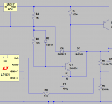
Here is an idea- if we add two diodes in series (D6 and D7 below) from the output to the LM317(337) V ref terminal when the current requirements exceed a threshold based on the emitter-base junction of Q1 it clamps the regulator and pulls the supply down. Its not ideal but in the simulation the regulation works to about 75 mA and then limits the power in the pass device to less than one watt. Its important to mix the diodes correctly. Two 1n914 types won't work. I'm using a Shottky diode for one to get the lower forward drop but more than one junction. A germanium diode would also work. . . The right LED might also work but even the IR LED's I checked needed more forward drop that would work here.
Here is an idea- if we add two diodes in series (D6 and D7 below) from the output to the LM317(337) V ref terminal when the current requirements exceed a threshold based on the emitter-base junction of Q1 it clamps the regulator and pulls the supply down. Its not ideal but in the simulation the regulation works to about 75 mA and then limits the power in the pass device to less than one watt. Its important to mix the diodes correctly. Two 1n914 types won't work. I'm using a Shottky diode for one to get the lower forward drop but more than one junction. A germanium diode would also work. . . The right LED might also work but even the IR LED's I checked needed more forward drop that would work here.
Attachments
The stability problem with the LM337 could be caused by the output bypass capacitor. A very low ESR here can create problems. The datasheet recommends a "1 μF solid tantalum or 10 μF aluminum electrolytic".
I once made a design using an LM337L with a ceramic capacitor on the output. It was not stable. Then I added a 1 ohm resistor in series with the capacitor and it worked fine.
I once made a design using an LM337L with a ceramic capacitor on the output. It was not stable. Then I added a 1 ohm resistor in series with the capacitor and it worked fine.
The stability problem with the LM337 could be caused by the output bypass capacitor. A very low ESR here can create problems. The datasheet recommends a "1 μF solid tantalum or 10 μF aluminum electrolytic".
I once made a design using an LM337L with a ceramic capacitor on the output. It was not stable. Then I added a 1 ohm resistor in series with the capacitor and it worked fine.
A quick check is to put 1 ohms in series with that output cap. If the oscillation stops, it's the lack of ESR.
Has bitten me more than I care to admit.
You're so used to using the best caps you can find that you forget that in cases like this you need some ESR.
Just the other day I received a new product announcement (I think it was TI) on some low dropout regs where they were actually bragging that they were stable even with low or no ESR output caps.
jan
It is a Nichicon muse I stuck in there that worked. That's what I had. Yes sometimes a high ESR is what's needed. I did have that in the back of my mind when I put in the oscon. The 337s seems to enjoy more capacitance than what the data sheet prescribes but I don't think this is so for the 317. They are different animals with like spots.
I got tired of having to replace tantalum in my Twin T which runs on batteries. What was happening is one battery collapsed before the other. The op amps pulled the dead rail to the opposite rail putting a reverse voltage across the bypass caps and boom. The trick I use now is to place a small diode reverse biased on each rail. If one rail is lost the diode limits the reverse voltage across the bypass caps. I do this on analog supplies as well. Not in the power supply but on the load board.
I got tired of having to replace tantalum in my Twin T which runs on batteries. What was happening is one battery collapsed before the other. The op amps pulled the dead rail to the opposite rail putting a reverse voltage across the bypass caps and boom. The trick I use now is to place a small diode reverse biased on each rail. If one rail is lost the diode limits the reverse voltage across the bypass caps. I do this on analog supplies as well. Not in the power supply but on the load board.
Here is an idea- if we add two diodes in series (D6 and D7 below) from the output to the LM317(337) V ref terminal when the current requirements exceed a threshold based on the emitter-base junction of Q1 it clamps the regulator and pulls the supply down. Its not ideal but in the simulation the regulation works to about 75 mA and then limits the power in the pass device to less than one watt. Its important to mix the diodes correctly. Two 1n914 types won't work. I'm using a Shottky diode for one to get the lower forward drop but more than one junction. A germanium diode would also work. . . The right LED might also work but even the IR LED's I checked needed more forward drop that would work here.
Sure but we cant rely on the transistor failing the same way every time. I was lucky twice.
Best solution is, don't short the output. This isn't a product that expects idiot proofing.
I like the socket idea and keeping it simple.
")
- Home
- Design & Build
- Equipment & Tools
- Low-distortion Audio-range Oscillator