

Oscillator power supply
Hi guys,
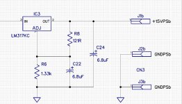
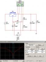
I have a rather curious problem with LM317. I'm using this as a pre regulator in front of Demian's regulator. The 317 is exhibiting a strong pulse every 64us at about +/- 1mV. It looks like a differentiated pulse rising and falling followed by an up ramp, then it repeats.
I'm wondering if maybe the components I used are a bit to stiff. The set resistor is 121 ohm
and I used 6.8uF oscon filter caps. Does a high ESR cap work better here? Is the set current set to high? Input is unloaded 30V and output is 15V for example shown. The load has no influence on the behavior.
Hi guys,
I have a rather curious problem with LM317. I'm using this as a pre regulator in front of Demian's regulator. The 317 is exhibiting a strong pulse every 64us at about +/- 1mV. It looks like a differentiated pulse rising and falling followed by an up ramp, then it repeats.
I'm wondering if maybe the components I used are a bit to stiff. The set resistor is 121 ohm
and I used 6.8uF oscon filter caps. Does a high ESR cap work better here? Is the set current set to high? Input is unloaded 30V and output is 15V for example shown. The load has no influence on the behavior.
Attachments
Last edited:
Hi guys,
I have a rather curious problem with LM317. I'm using this as a pre regulator in front of Demian's regulator. The 317 is exhibiting a strong pulse every 64us at about +/- 1mV. It looks like a differentiated pulse rising and falling followed by an up ramp, then it repeats.
I'm wondering if maybe the components I used are a bit to stiff. The set resistor is 121 ohm
and I used 6.8uF oscon filter caps. Does a high ESR cap work better here? Is the set current set to high? Input is unloaded 30V and output is 15V for example shown. The load has no influence on the behavior.
Interesting. Is exactly the line frequency of a vintage tube monitor screen....
Jan
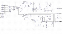
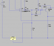
It seems if I remove all the load resistors the problem stops. I'll include the entire schematic.
I have two +/- supplies on one board. The pulse is cross talking to the second supply regulator making it hard to track it down. I don't think it coming from the LM317 now.
I have two +/- supplies on one board. The pulse is cross talking to the second supply regulator making it hard to track it down. I don't think it coming from the LM317 now.
Attachments
Hi guys,
I have a rather curious problem with LM317. I'm using this as a pre regulator in front of Demian's regulator. The 317 is exhibiting a strong pulse every 64us at about +/- 1mV. It looks like a differentiated pulse rising and falling followed by an up ramp, then it repeats.
I'm wondering if maybe the components I used are a bit to stiff. The set resistor is 121 ohm
and I used 6.8uF oscon filter caps. Does a high ESR cap work better here? Is the set current set to high? Input is unloaded 30V and output is 15V for example shown. The load has no influence on the behavior.
First- not all 317's are alike so a different vendors version may work differently. The current through Vadj is in the microamps so it won't be affected much by the lower impedance. Typically I have reverse protection diode and cap (per pg 4 of this datasheet: http://www.onsemi.com/pub_link/Collateral/LM317-D.PDF ).
Is the pulse also visible on the Vref terminal? If you add the cap bypassing the resistor to ground does the pulse still exist on the output? I have never seen a sensitivity to ESR with an LM317 and I have tried very low esr. Are you approaching the thermal limits of the device?
Hi Demian,
There is no pulse on the supply that operates on with just 317. Mind you it was unloaded when I tested it and I should try it with a load.. I blew my ac input fuse and I don't have another low current fuse. I have to go get more. So testing ais halted at the moment.
I suspect the TL431 is oscillating. I've seen this before using them as just a simple shunt regulator oscillating at the reference pin right about 15kHz. 64us is just around there at 15.625kHz. I have to reduce the supply to just the positive regulator. Shut everything else down. The board is designed to configure the 317/337 for tracking or fixed operation. I configured the 317 for the positive pre regulator supply for fixed reference. This made no difference. When I removed the loads the pulse stopped. But then the regulator doesn't function properly. I no longer suspect the 317 as being the problem. All I see is just the regular noise that's typical of them.
It seems if I remove all the load resistors the problem stops. I'll include the entire schematic.
I have two +/- supplies on one board. The pulse is cross talking to the second supply regulator making it hard to track it down. I don't think it coming from the LM317 now.
Might be opamps ---- change opamps to 741. or put .1-.22 bypass caps close to the opamp + and - pins.... see if osc stops.
-RNM
Last edited:
First- not all 317's are alike so a different vendors version may work differently. The current through Vadj is in the microamps so it won't be affected much by the lower impedance. Typically I have reverse protection diode and cap (per pg 4 of this datasheet: http://www.onsemi.com/pub_link/Collateral/LM317-D.PDF ).
Is the pulse also visible on the Vref terminal? If you add the cap bypassing the resistor to ground does the pulse still exist on the output? I have never seen a sensitivity to ESR with an LM317 and I have tried very low esr. Are you approaching the thermal limits of the device?
All the large components are on heat sinks. There is not even detectable heat coming from the 317 or the output transistor. I had a 3k load on the output. It's possible there may be oscillation from the complementary pair output stage. They can be sensitive to capacitive loading. I'll remove the 10uF output caps and see what happens. Might have to add an inductor for isolation of the C.
At any rate I have to go and get more fuses.
Do you have it near an LCD monitor? The ESR of the output cap is too low and it's being excited into oscillation -- the folks at Omicron Lab have a youtube on choosing the right device, but off hand a 120uF 25V Panasonic FC works for me.I have a rather curious problem with LM317. I'm using this as a pre regulator in front of Demian's regulator. The 317 is exhibiting a strong pulse every 64us at about +/- 1mV. It looks like a differentiated pulse rising and falling followed by an up ramp, then it repeats.
OMICRON Lab "Smart Measurement Solutions": Non-invasive Stability
It might not even be necessary to bypass the ADJ pin because the output noise will be dominated by the Demian regulator.
split supply
I checked the examples I have on the bench for any oscillation and can't see any.
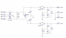
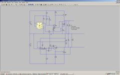
Here is a revision based on an idea I have had lurking for some time. Note where the 3 terminal regulators are connected. Since its a spice model I can't be sure it works the same in real life but it really should.
I checked the examples I have on the bench for any oscillation and can't see any.
Here is a revision based on an idea I have had lurking for some time. Note where the 3 terminal regulators are connected. Since its a spice model I can't be sure it works the same in real life but it really should.
Attachments
Hi Guys,
Any thoughts on using IR remote for tuning and level setting an oscillator?
It's not too difficult to do and offers complete isolation. No PC control required.
It's certainly a lot less expensive than control knobs and switches for manual control.
There's not a lot of USB bandwidth required for control so a USB IR stick could be make to work for PC control.
How do you do that without a switch?
David-
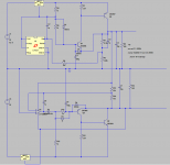
On your schematic (which seems to have a few errors) you have a cap C13 47 uF. In playing with the simulation I found the best performance with that being 1uF in series with 100K. There may be a phase margin issue at play here.
I noticed a mistake in the last drawing I posted. The negative regulator is tied to the drive for the amplifying transistor. That keeps the transistor out of saturation. I was having some trouble getting the 337 model working and did not notice this error.
Attachments
Might be opamps ---- change opamps to 741. or put .1-.22 bypass caps close to the opamp + and - pins.... see if osc stops.
-RNM
It's oscillating on the positive supply not the negative. No op amp except for the TL431.
The negative supply is driven from the output of the positive.
Interesting. Is exactly the line frequency of a vintage tube monitor screen....
Jan
Hi Jan,
My monitor is up to date. But it's an interesting suggestion about outside source of interference. Could still be the monitor. My modem is 14.45mHz burst tone so I know it's not that. The power supply goes nuts with noise anytime I move the wireless mouse.
Haven't got it in an enclosure yet. Just easier to work on it this way.
Might be opamps ---- change opamps to 741. or put .1-.22 bypass caps close to the opamp + and - pins.... see if osc stops.
-RNM
I'm using an OP27. It's has a slew rate about the same as a 741 but with a lot less noise.
OP27 has a very low 1/f noise which is good for DC supply.
How do you do that without a switch?
Relays and Mdacs. I meant front panel mounted switches.
I checked the examples I have on the bench for any oscillation and can't see any.
Here is a revision based on an idea I have had lurking for some time. Note where the 3 terminal regulators are connected. Since its a spice model I can't be sure it works the same in real life but it really should.
What specific errors in the schematic?
David-
On your schematic (which seems to have a few errors) you have a cap C13 47 uF. In playing with the simulation I found the best performance with that being 1uF in series with 100K. There may be a phase margin issue at play here.
I noticed a mistake in the last drawing I posted. The negative regulator is tied to the drive for the amplifying transistor. That keeps the transistor out of saturation. I was having some trouble getting the 337 model working and did not notice this error.
You had no in series with that cap. I increased it to 47u and changed that to 39u.
It slows the integrator down but improves the noise and ripple rejection.
I don't mind the settling a bit slower.
Anyway that's not where the issue is. The problem is on the positive supply.
This is the last drawing I got from you.
Attachments
Last edited:
- Home
- Design & Build
- Equipment & Tools
- Low-distortion Audio-range Oscillator