Demian.... it isnt relavent to these pictures. You only need to see the 3H is lower in some analyzers -compared to the 2H. It could be 10% THD... or .001% THD it doesnt matter.
[I also did as you suggested already and pointed out some interactions with that signal a few lines back.]
Here, I dont care what the absolute levels are. I am showing differences in the recovered Harmonic levels for the same input voltage/source/freq.
If the 2H and 3H do not have the same relationship in level to each other then what are some of the possible explanations for it ?
With the 725, the 2H and 3H are at similar levels to each other. With the other analyzers, the 2H is much higher than the 3H.
Thx-RNMarsh
Rick the 339a has a variable capacitor for adjusting mid to high frequency flatness.
Calibrate the analyzer at 20kHz.
Basically when it come to distortion measurements we're screwed.
Pretty sure
 ; at least when residuals from source and THD analyzer have comparable levels. Using two analyzers based on different topologies and/or technologies helps to figure out the problem, but doesn't solve it.
Here is what I get when I look at residuals of my 239A clone thru a double Bainter notch or a SVF notch with auto nulling with the same post-notch gain (40dB): the two notches agee on the level of 3rd h, but the latter overestimate (or the former underestimate?) the level of 2nd h. When measuring sources of higher THD (eg the true 239A) the agreement between the two notches is almost perfect.
L.
Attachments
Last edited:
Rick the 339a has a variable capacitor for adjusting mid to high frequency flatness.
Calibrate the analyzer at 20kHz.
I'll check it and see if that brings it up. But the other (7722) has same issue... however, they will sell me a service manual to see what is going on inside and what adjustments there might be for ?? Its on the way.
Thx-RNM
Well, I'm quite desperate as I've tried to explain this issue probably half a dozen times now... Apparently I can not phrase this good enough. Surely this text (page 44ff) does better:
http://cds.linear.com/docs/en/application-note/an43f.pdf
In particular make sure you follow the section on "Distortion Measurement Accuracy".
Samuel
OK OK I got it. they could add or subtract or partially either. But there's more... comment tomorrow... going blind at the screen at 1:30am
-RNm
You can separate frequency response issues from constructive/destructive harmonic issues using the "marker" to verify the response of the notch filter circuit. If you get artifacts when connecting a marker its probably grounding issues.
Most of the analyzers I have checked have response to harmonics as high as 500 KHz when no filters are engaged. Some (The KH distortion analyzers in particular) have tracking filters that limit the response to harmonics to something like 5 or 10 but that is the exception. You can quickly evaluate this using a square wave or triangle wave which will get a "rich" collection of harmonics with pretty well defined spectral distribution.
Most of the analyzers I have checked have response to harmonics as high as 500 KHz when no filters are engaged. Some (The KH distortion analyzers in particular) have tracking filters that limit the response to harmonics to something like 5 or 10 but that is the exception. You can quickly evaluate this using a square wave or triangle wave which will get a "rich" collection of harmonics with pretty well defined spectral distribution.
It seems to me that if you want to accurately measure very low level harmonic distortions, there may be a way to do it.
You need to have at least two identical oscillators that then are injection locked to a stable reference. However one should be locked through a variable phase shift network. You can use a lissajous pattern to verify the phase shift. Now set one oscillator as the unit under test. The other can be set to the harmonic under test (2nd, 3rd etc,) Using a precision attenuator you can then null the harmonic or even double it. So you will know to a reasonable level of accuracy, the attenuated level required to match the harmonic under test. Not simple or quick, but it should allow determination of the distortion levels.
ES
It seems to me that if you want to accurately measure very low level harmonic distortions, there may be a way to do it.
You need to have at least two identical oscillators that then are injection locked to a stable reference. However one should be locked through a variable phase shift network. You can use a lissajous pattern to verify the phase shift. Now set one oscillator as the unit under test. The other can be set to the harmonic under test (2nd, 3rd etc,) Using a precision attenuator you can then null the harmonic or even double it. So you will know to a reasonable level of accuracy, the attenuated level required to match the harmonic under test. Not simple or quick, but it should allow determination of the distortion levels.
And how do you check if the harmonics cancel?
Samuel
And how do you check if the harmonics cancel?
Samuel
Excellent question!
If you are looking for a peak, I would use a synchronous injection locked variable phase amplifier with a passive filter. By varying the phase you should be able to identify each component.
If looking for a null most high resolution methods would do. If your measurement system is doing it's own bit of distortion cancellation you should have two nulls. If the distortions are adding, only one. So there you might also vary the phase of the oscillator under test.
ES
Last edited:
It would be a slow process harmonic by harmonic. And in the end you may not be able to use the info for anything.
Of course it is a slow process!
But the recursion here is to build a better oscillator so we can test our distortion tester. The real issue is getting well matched oscillators. That would require reciprocity.
Just because the oscillators match well at one frequency doesn't mean at the harmonic it is the same.
This is certainly not a method for the faint of heart. It is intended as a thought exercise.
ES
Pretty sure
Here is what I get when I look at residuals of my 239A clone thru a double Bainter notch or a SVF notch with auto nulling with the same post-notch gain (40dB): the two notches agee on the level of 3rd h, but the latter overestimate (or the former underestimate?) the level of 2nd h. When measuring sources of higher THD (eg the true 239A) the agreement between the two notches is almost perfect.
L.
This indicates the analyzer was getting a bit nonlinear at very low levels? Then at what level, for your system, is it accurate or become inaccurate?
-RNM
Last edited:
So far, I've found that some several measuring systems have greater resolution than they have accuracy. Meaning -- the last digit or lowest ranges' levels shown/displayed are not accurate enough to use with confidence.
IMO, arduous tests to determine the absolute level and accuracy of the harmonics measured will show this or that for given level(s) and topology. BUT, the more useful finding to come out of this test will be the discovery of what causes the non-linear response -errors- to the low level harmonic structure. is there a dominant culprit?
Is it a converter being used? Like an ac -> dc. Then can we improve on it somehow? Or, is it the phase interference from the notch, itself? That is, if the notch wasnt there, would the harmonic structure still be affected? If it is an aboration due to the phase thru the notch region interacting with the phase of the harmonic(s), then what to do about it.
One would be, as I've mentioned before, is to raise the notch Q so the phase transition region is more narrow.
Thx-RNMarsh
Last edited:
Input a waveform with a set of known harmonics may tell something about the analyzer. For example, input a square waveform and measure the magnitude of the harmonics. If the analyzer is adding or subtracting harmonics the know harmonic level will be different. A triangular wave form might be easier. A low level marker, as Demian suggested, could be swept slowly to see level flatness.
Aside form harmonic cancellation it might be a case of level flatness. Some filters have ripple in their stop bands. Ripple can occur from pole interaction of long cascades of amplifiers, filter stages etc. including external sources. These interactions can be quite different at -120dB than say -20dB.
This is why I think the shortest change of amplifiers, filters etc is best. The less involved the more accurate the measurement. Manufactures spend a great deal of time on the above mentioned but they can't control or account for the external.
Last edited:
Hasnt this been done before? Harmonic level checking... surely the mfr would have done so and got the response as flat as possible. Anyone out there in the ether zone done this?
I have plenty of function gens and osc to try it. How about the notch/FFT/ADC guys... have they checked thier systems out this way? I recall correction for attenuation of mostly 2H and some 3H from affects of notch. That doesnt explain all of it, though. Not why the 3H is lower than the 2H on some analyzers and not the others, etc. Still seems like phase issues, so far.
Thx-RNMrash
Last edited:
If you are looking for a peak, I would use a synchronous injection locked variable phase amplifier with a passive filter. By varying the phase you should be able to identify each component.
If looking for a null most high resolution methods would do. If your measurement system is doing it's own bit of distortion cancellation you should have two nulls. If the distortions are adding, only one. So there you might also vary the phase of the oscillator under test.
Well, if we had a high resolution method to begin with we would not need to look any further. Unfortunately, high resolution in the context of distortion measurement does not only mean a low noise/narrow bandwidth analyzer, but also one with low harmonic distortion--distortion of the analyzer is also a form of resolution limitation. Lock-in techniques surely fit the low noise/narrow bandwidth criteria, but are unlikely to offer very low distortion. Also I don't see how two null conditions could exist..?
IMO, arduous tests to determine the absolute level and accuracy of the harmonics measured will show this or that for given level(s) and topology. BUT, the more useful finding to come out of this test will be the discovery of what causes the non-linear response -errors- to the low level harmonic structure. is there a dominant culprit?
Is it a converter being used? Like an ac -> dc. Then can we improve on it somehow? Or, is it the phase interference from the notch, itself? That is, if the notch wasnt there, would the harmonic structure still be affected? If it is an aboration due to the phase thru the notch region interacting with the phase of the harmonic(s), then what to do about it.
The overall distortion behaviour of an analyzer is probably even more complex than that of a generator, because the circuit complexity is usually higher. But the usual suspects are the same: passives, amplifiers, multipliers, control voltage ripple and layout effects.
Aside form harmonic cancellation it might be a case of level flatness. Some filters have ripple in their stop bands. Ripple can occur from pole interaction of long cascades of amplifiers, filter stages etc. including external sources. These interactions can be quite different at -120 dB than say -20 dB.
This is why I think the shortest change of amplifiers, filters etc is best. The less involved the more accurate the measurement. Manufactures spend a great deal of time on the above mentioned but they can't control or account for the external.
I don't see why the filter response should depend on the level. This would mean drastic nonlinearity, which hopefully is not the case. Poor ADCs might show unexpected low-level nonlinearity (e.g. because of improper dithering), though.
Measuring low distortion is mostly a resolution problem, not an accuracy problem.
Hasnt this been done before? Harmonic level checking... surely the mfr would have done so and got the response as flat as possible. Anyone out there in the ether zone done this?
I have plenty of function gens and osc to try it. How about the notch/FFT/ADC guys... have they checked thier systems out this way? I recall correction for attenuation of mostly 2H and some 3H from affects of notch. That doesnt explain all of it, though. Not why the 3H is lower than the 2H on some analyzers and not the others, etc. Still seems like phase issues, so far.
With an active notch filter flatness should not usually be a problem up to ~100 kHz; I've used white noise to determine the exact notch shape (with a sweeped sine I'd expect the notch to track the signal, so the frequency response might change during the sweep). With the passive notch filters I'm measuring the frequency response of the chain. Without that, a few minor dB might creep in.
Samuel
Well, if we had a high resolution method to begin with we would not need to look any further. Unfortunately, high resolution in the context of distortion measurement does not only mean a low noise/narrow bandwidth analyzer, but also one with low harmonic distortion--distortion of the analyzer is also a form of resolution limitation. Lock-in techniques surely fit the low noise/narrow bandwidth criteria, but are unlikely to offer very low distortion. Also I don't see how two null conditions could exist..?
Samuel
I think this is a use of language issue. I believe we are in agreement you can reduce the noise/bandwidth issue and the real problem lies in the meter chain distortion.
When you sweep the cancellation oscillator there will be a dip when it inversely matches the oscillator under test. There will be another dip where it inversely matches the distortion mechanism of the meter chain. The case where the phase of the meter chain distortion matches exactly the oscillator under test would result of course in a single null.
That is why you would also want to do a measurement of where the distortion doubles. Unless the mechanism for the meter chain distortion is identical to the oscillator under test the results will differ.
If you are using a DSP device to make the measurement changing level slightly or adding noise (sometimes noise can be your friend!) will help to differentiate the two distortion mechanisms, as they most likely come from two different source mechanisms.
The idea is to have a method to determine if changes made to the design under test are actually decreasing the distortion. For publication the higher distortion number could be safely used.
ES
When you sweep the cancellation oscillator there will be a dip when it inversely matches the oscillator under test. There will be another dip where it inversely matches the distortion mechanism of the meter chain. The case where the phase of the meter chain distortion matches exactly the oscillator under test would result of course in a single null.
I don't see why this should happen. If you adjust the cancellation signal to exactly cancel the oscillator harmonic, the harmonic distortion of the analyzer will remain--no null. Same vice versa. The only true null occurs when the cancellation signal cancels the sum of the oscillator and analyzer harmonic--which means that we're limited again by the resolution of the analyzer, i.e. where we started...
One could cancel the fundamental of the oscillator under test with a phase-locked and "known much lower distortion" second oscillator. This would resolve the resolution issue of the analyzer, but mitigates the problem to having a "known much lower distortion" oscillator...
Samuel
Filters must be exact -
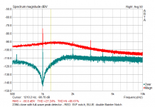
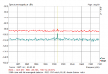
OK. I ran the analyzer with dual freqs.... 1Khz/1v The other freq was passively mixed in with a precision 1000:1 atten. The osc were the 339A for the main freq osc and the AG16 ShibaSoku osc for its precision atten and freq adjustablity.
The AD725D was flat across the first 5 harmonics.
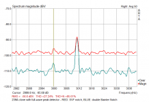
But, it did point out how important the tracking must be between osc and analyzer. If the harmonic freq filter is a fraction of a percent off of the fund freq, the harmonic level drops fast (very high Q). How much? See attached:


Just One percent difference is a disaster... big drop in measurement level.
Thx-RNMarsh
OK. I ran the analyzer with dual freqs.... 1Khz/1v The other freq was passively mixed in with a precision 1000:1 atten. The osc were the 339A for the main freq osc and the AG16 ShibaSoku osc for its precision atten and freq adjustablity.
The AD725D was flat across the first 5 harmonics.
But, it did point out how important the tracking must be between osc and analyzer. If the harmonic freq filter is a fraction of a percent off of the fund freq, the harmonic level drops fast (very high Q). How much? See attached:
Just One percent difference is a disaster... big drop in measurement level.
Thx-RNMarsh
Last edited:

I don't see why the filter response should depend on the level. This would mean drastic nonlinearity, which hopefully is not the case. Poor ADCs might show unexpected low-level nonlinearity (e.g. because of improper dithering), though.
Measuring low distortion is mostly a resolution problem, not an accuracy problem.
Samuel
Level has nothing to do with filter response. If you cascade a number of same type filters all tuned to the same frequency a ripple will appear both in the pass band and stop band. The reason for this is the pole are very close or on top of one another.
I deal with this at work where Long cascades of wideband RF amplifiers are used. The amplifiers have diplex filters at each end, input and output, and after a cascade of four or more amplifiers passband ripple is present and become worse as more amplifiers are added to the cascade. This is what I'm getting at.
I've done sweep tests with the EmU0204 and QA400. Below -120dB things get weird.
I'm not suggesting a cause, it's just an observation.
- Home
- Design & Build
- Equipment & Tools
- Low-distortion Audio-range Oscillator