Sorry for the non-sequitur. Too many open windows.
I take it that wasn't supposed to go here.
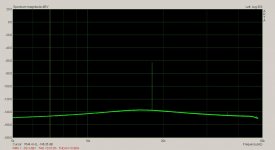
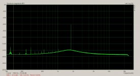
Here is something also interesting... I have compared the THD of two analyzers using the same source generator. They gave similar THD figures but as you can see in the photos... one is showing a 2H dominant and the other its a 3H! Now how can I tell there isnt some sort of timing error in setup display (didn't change any settings)...
Both can indicate the level of the individual harmonic I choose. And as the residual display showed, the analyzer indicated the Harmonic which was highest was the one shown via the residual monitor output port.
Impedance interaction with generator z on the analyzer inputs? I tried adding 1K in series with each analyzer input but the Harmonic level and freq disnt change. Got any ideas... Cockpit error or?
Now we're getting somewhere! As you've now discovered yourself (apparently external interventions didn't help
") ), a distortion analyzer does have its own distortion contribution, which interacts with the DUT. And that's not limited to input/output impedance interactions. The distortion contribution of the analyzer is not some sort of offset which we can measure and then subtract out, as done for a DC voltage measurement. The distortion contribution is a very strong, and complex, function of the operating conditions of the analyzer (frequency, level, range settings, source Z, amount of RF interference present etc.). This all is way too complex, and sufficiently inconsistent, to model. So the best bet is to design a (probably passive) notch filter which one can expect to perform much better than the oscillator under test. That's of course a classic chicken-egg problem--to verify the notch filter you need an oscillator with known much better distortion performance, and vice versa.
), a distortion analyzer does have its own distortion contribution, which interacts with the DUT. And that's not limited to input/output impedance interactions. The distortion contribution of the analyzer is not some sort of offset which we can measure and then subtract out, as done for a DC voltage measurement. The distortion contribution is a very strong, and complex, function of the operating conditions of the analyzer (frequency, level, range settings, source Z, amount of RF interference present etc.). This all is way too complex, and sufficiently inconsistent, to model. So the best bet is to design a (probably passive) notch filter which one can expect to perform much better than the oscillator under test. That's of course a classic chicken-egg problem--to verify the notch filter you need an oscillator with known much better distortion performance, and vice versa.Samuel
I have been messing around with these analyzers all day long and now all night as well. I finally focused on just one -- The ShibaSoku AD725D analyzer.
using a seperate generator's attenuated freq and mixing it in with a resistive network with the main generator (DUT) to do a check on the calibration of the system --- I tuned the calibration freq via the analyzers selected 5H and tuned freq to peak level and adjusted the overall level for full scale on a particular scale like -100dB. Then monitored the residual output of the main generator under test with the HP spectrum analyzer.
The front panel display is accurate within spec'ed tolerance to -125dB. And still reasonably accurate at monitor port to -135dB. Between -135 and -140dB is a 50-50 estimate. This is where an FFT box could see further into the noise.
It was noticed too that when the cal signal level was set to full scale, there were extrainious artifacts/freqs introduced into the measurement of the DUT generator. So, though useful for calibrating full scale as a reassuring check, it has to be reduced in amplitude for the actual measurement -Staying in the middle of the range is most accurate area to set the operation.
But being able to see harmonics this low in level and it was designed decades ago is still an impressive feat. Now to finally apply FFT to the residual port... .
Samuel... it wasnt that i wasnt listening... just the info was too broad and I needed specifics to my test gear/arrangment etc. But the warning was in the back of my mind.
Thx-RNMarsh
Last edited:
Now we're getting somewhere!
So the best bet is to design a (probably passive) notch filter which one can expect to perform much better than the oscillator under test. That's of course a classic chicken-egg problem--to verify the notch filter you need an oscillator with known much better distortion performance, and vice versa.
Samuel
The main difference between similar THD analyzers/meters is the notch --- its Q and its depth. This is where the AD725D excells and allows me to see closely spaced details and to a much greater depth. I would focus on this area more and then work to solve any spin-off issues from it. A comination of passive and active might arrive at best/optimized performance.
The only thing limiting the AD725D now is the use of comparatively noisy opamps of the past - compared to today's best. If I can lower the noise of the analyzer and its filters then I can look to lower levels of oscillator or other DUT directly. So this is the other point -- noise must be kept as low as possible. Then the application of FFT/averaging will drop us even more... and still remain accurate - without added spurious freqs. to contend with. But first the fundamentals need to be improved/done to best possible.
THx-RNMarsh
Last edited:
For the oscillator, it must be able to vary its freq by +/- 5-10%.... via a vernier adjustment.
Because if the osc freq and the thd meter notch freq are not exactly the same, an inaccurate THD reading will occure. This is especialy true when the notch is very,very sharp/very high Q.
All the commercial oscillator and combo osc/thd meter I have seen have this feature.
Thx-RNMarsh
Because if the osc freq and the thd meter notch freq are not exactly the same, an inaccurate THD reading will occure. This is especialy true when the notch is very,very sharp/very high Q.
All the commercial oscillator and combo osc/thd meter I have seen have this feature.
Thx-RNMarsh
Last edited:
The main difference between similar THD analyzers/meters is the notch --- its Q and its depth. This is where the AD725D excells and allows me to see closely spaced details and to a much greater depth. I would focus on this area more and then work to solve any spin-off issues from it. A comination of passive and active might arrive at best/optimized performance.
The only thing limiting the AD725D now is the use of comparatively noisy opamps of the past - compared to today's best. If I can lower the noise of the analyzer and its filters then I can look to lower levels of oscillator or other DUT directly. So this is the other point -- noise must be kept as low as possible. Then the application of FFT/averaging will drop us even more... and still remain accurate - without added spurious freqs. to contend with. But first the fundamentals need to be improved/done to best possible.
THx-RNMarsh
Careful with the analyzers Rick. All the compensations of the amplifiers were chosen for level flatness and bandwidth. If you change op amps in an analyzer like the 725 you have to calibrate it at the same time. This holds true for the 339a as well. Changing the op amps messes with the bandwidth and bandwidth changes can alter what the unit reports.
Careful with the analyzers Rick. All the compensations of the amplifiers were chosen for level flatness and bandwidth. If you change op amps in an analyzer like the 725 you have to calibrate it at the same time. This holds true for the 339a as well. Changing the op amps messes with the bandwidth and bandwidth changes can alter what the unit reports.
I agree... found out with the others, also. In those I didnt care if they didnt run to 100KHz.... Just to 10KHz if the thd and noise was better.
So, the best thing i can do is not mess with the analyzer itself but the filters and residual monitor circuits and the like... they use TLO7x, for example. Those circuits between me and the analyzer. See what this accomplishes... .
Thx-RM
Last edited:
The main difference between similar THD analyzers/meters is the notch--its Q and its depth. This is where the AD725D excells and allows me to see closely spaced details and to a much greater depth. I would focus on this area more and then work to solve any spin-off issues from it. A comination of passive and active might arrive at best/optimized performance.
Notch depth is not of cruical importance for a THD measurement (it is for THD+N, though). 60 dB is usually sufficient if the following THD analyzer (either a conventional auto-tuning notch or directly a ADC) is of good quality. My setup is a fixed frequency passive notch filter with > 60 dB fundamental rejection, 40 dB low-distortion/low noise preamp, AP SYS-2722 analog notch filter, AP SYS-2722 ADC. It would also be possible to skip the analog notch filter and feed the preamp output directly to the ADC.
Samuel
How's this for almost 20kHz.
The lamp multiplier didn't work out. Too microphonic when the lamps are hot.
I moved on to another multiplier idea of mine which is rather unusual.
Very good !
I agree.Notch depth is not of cruical importance for a THD measurement (it is for THD+N, though).
Samuel


What would help a lot would be to add a marker at a known level, say -120 dBC. You will need some matching/mixing network that matches impedances and levels. The attenuator on the KH or the AG16 should be good enough once the basics are established. Victor suggested this idea. I tried it and it works well. It won't show on the analysis output of the 725D. I even tried to match the frequency of a harmonic. You could easily see the beats.
Demian.... it isnt relavent to these pictures. You only need to see the 3H is lower in some analyzers -compared to the 2H. It could be 10% THD... or .001% THD it doesnt matter.
[I also did as you suggested already and pointed out some interactions with that signal a few lines back.]
Here, I dont care what the absolute levels are. I am showing differences in the recovered Harmonic levels for the same input voltage/source/freq.
If the 2H and 3H do not have the same relationship in level to each other then what are some of the possible explanations for it ?
With the 725, the 2H and 3H are at similar levels to each other. With the other analyzers, the 2H is much higher than the 3H.
Thx-RNMarsh
Last edited:
If the 2H and 3H do not have the same relationship in level to each other then what are some of the possible explanations for it?
With the 725, the 2H and 3H are at similar levels to each other. With the other analyzers, the 2H is much higher than the 3H.
Well, I'm quite desperate as I've tried to explain this issue probably half a dozen times now... Apparently I can not phrase this good enough. Surely this text (page 44ff) does better:
http://cds.linear.com/docs/en/application-note/an43f.pdf
In particular make sure you follow the section on "Distortion Measurement Accuracy".
Samuel
- Home
- Design & Build
- Equipment & Tools
- Low-distortion Audio-range Oscillator